Supercharge Your Innovation With Domain-Expert AI Agents!

Method for optimization of dispersion compensation, transponder and its use in an optical network with path protection

a technology of optical data network and optimization method, applied in multiplex communication, electromagnetic transmission, instruments, etc., can solve the problems of short restoration time, large time required for such adjustment, and large time requirement, so as to improve network performance immediately after switching, short restoration time, and quick and easy realization

Inactive Publication Date: 2006-10-12
ALCATEL LUCENT SAS
View PDF4 Cites 3 Cited by
  • Summary
  • Abstract
  • Description
  • Claims
  • Application Information

AI Technical Summary

Benefits of technology

The invention is a method for optimizing the operation of a network using a common tuneable dispersion compensator (TDC) for all paths. The method involves determining and storing optimized operating parameters for each path, which can be used to quickly adjust the network to a new path. The optimized parameters include information about the chromatic dispersion characteristics of each path, and the network can be adapted to changes in network characteristics over time. The method allows for fast restoration time and efficient path protection in a network. The invention also includes a transponder for an optical data network, which uses a common TDC for all ports and automatically adjusts to the optimized parameters when switching between ports. Overall, the invention improves network performance and provides better path protection in optical networks.

Problems solved by technology

However, the required time for such an adjustment is rather large, well above 10 seconds.
As a result, no measurements of dispersion characteristics of the path switched to are required for re-establishing the data transfer within the network, making the restoration time particularly short.

Method used


Image

  • Method for optimization of dispersion compensation, transponder and its use in an optical network with path protection
  • Method for optimization of dispersion compensation, transponder and its use in an optical network with path protection

Examples


Embodiment Construction

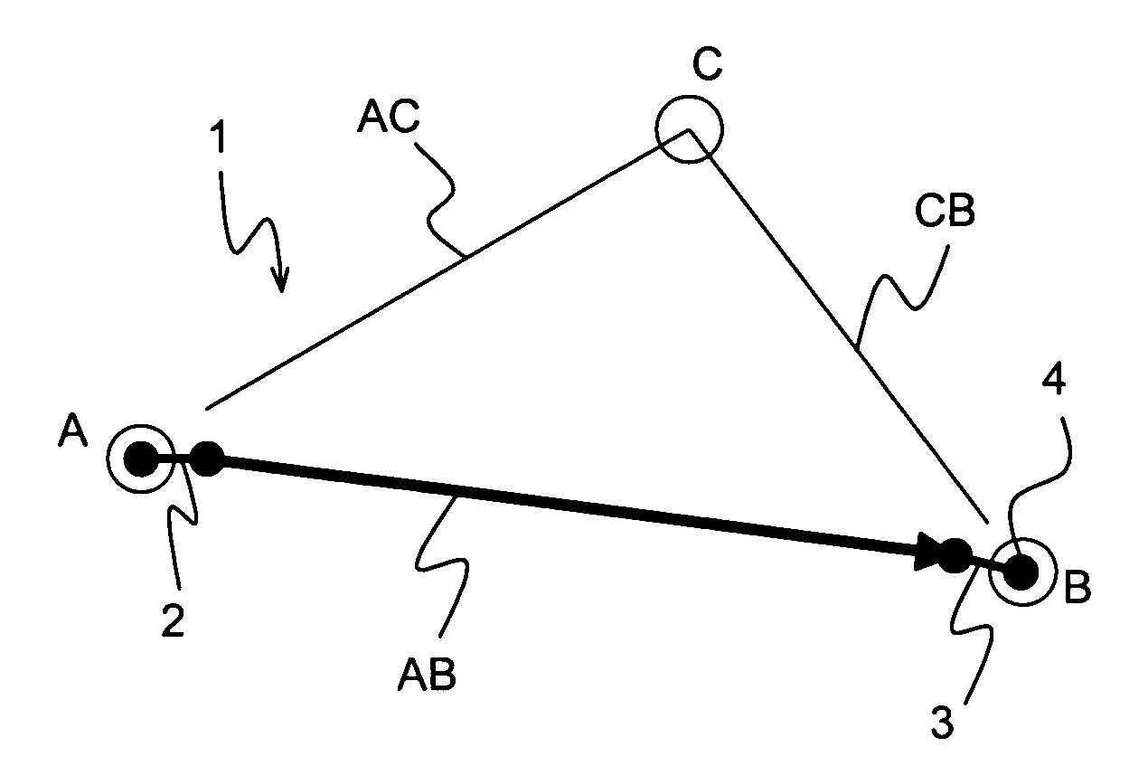
[0031]FIG. 1 shows an optical data network 1 with path protection and restoration in accordance with the invention. The network 1 comprises three nodes A, B and C, connected to each other by paths AB, AC and CB, respectively. The path lengths are 500 km for AB, 300 km for AC and 350 km for CB. The nodes A, B, C are suited for inserting data into the network 1 and reading out data from the network 1. The network 1 may comprise further nodes and corresponding connections (not shown).

[0032] The nodes A, B comprise optical switches 2, 3 for choosing a path for data to be transferred from node A to node B. Regularly, the direct path AB is used, being the shortest connection of node A and node B. In the state shown in FIG. 1, the switches 2, 3 are in their lower positions for the direct path AB. The data transfer rate is 40 Gbit / s.

[0033] Node B comprises a tunable dispersion compensator (=TDC) 4, which is connected to the right end of the switch 3. Thus, the TDC 4 is used in any positio...


PUM


Abstract

The invention relates to a method for optimization of dispersion compensation in an optical data network (1), the network (1) comprising two nodes (A, B), at least two paths (AB, ACB) connecting the two nodes (A, B), and means (2, 3) for switching between the paths (AB, ACB), characterized in that the network (1) comprises a common tuneable dispersion compensator (=TDC) (4) for all of the at least two paths (AB, ACB), that prior to use of the network (1), for each path (AB, ACB), a set of optimized operating parameters of the network (1) is determined and stored, wherein the operating parameters of the network (1) include operating parameters of the TDC (4), and that in use of the network (1), upon switching to a path (AB, ACB), the network (1) is automatically adjusted to a set of initial operating parameters based upon the set of predetermined operating parameters of the respective path (AB, ACB). The method requires only a simply designed optical data network, and at the same time allows a fast re-establishing of data transfer upon switching of paths in a 40 Gbit / s (or higher) system.

Description

[0001] The invention is based on a priority application EP 05290767.2 which is hereby incorporated by reference. FIELD OF THE INVENTION [0002] The invention relates to a method for optimization of dispersion compensation in an optical data network, the network comprising two nodes (A, B), at least two paths connecting the two nodes, and means for switching between the paths. BACKGROUND OF THE INVENTION [0003] Such a method is described in U.S. Pat. No. 6,674,935. [0004] Optical data networks, such as 10 or 40 Gbit / s networks, are used to transfer data at high speed over large distances in the order of hundreds of kilometers. Such a network comprises nodes, i.e. devices for accessing the network in order to read out data and / or feed data into the network. These nodes are linked to each other by data transfer lines. The connections between the nodes are called paths. Typically, each node is connected to several neighboring nodes. [0005] However, problems may occur when a path in the n...

Claims


Application Information

Patent Timeline
Patent Type & Authority Applications(United States)
IPC IPC(8): G06F15/173H04B10/2513
CPCH04B10/25133H04J14/0227H04J14/0283H04Q2011/0079H04Q2011/0045H04Q2011/0073H04Q11/0062
Inventor CHARLET, GABRIELDOUVILLE, RICHARD
Owner ALCATEL LUCENT SAS
Features
  • R&D
  • Intellectual Property
  • Life Sciences
  • Materials
  • Tech Scout
  • Unparalleled Data Quality
  • Higher Quality Content
  • 60% Fewer Hallucinations
Learn More