Modulated gap segmented antenna for inductively-coupled plasma processing system

a technology of inductively coupled plasma and module gap, which is applied in the direction of vacuum evaporation coating, coating, electric discharge lamps, etc., can solve the problems of significant increase in rf power and increase in problems, and achieve the effect of improving the uniformity of plasma processing on semiconductor wafers

Inactive Publication Date: 2006-10-19
TOKYO ELECTRON LTD
View PDF20 Cites 0 Cited by
  • Summary
  • Abstract
  • Description
  • Claims
  • Application Information

AI Technical Summary

Benefits of technology

[0013] An objective of the present invention is to improve the plasma processing uniformity on semiconductor wafers, particularly in applications involving etching or higher pressure coating processes.
[0015] Other objectives are to provide a plasma source for processing larger area substrates with uniform plasma processing, to provide a low inductance inductive device for such a source, and to provide a highly effective plasma source that is simplified and reduces overall chamber cost.

Problems solved by technology

Scaling up an external antenna for large area plasma in a conventional inductively coupled discharge meets such difficulties as thicker dielectric window to withstand atmospheric forces, and a higher inductance of antenna, significant increase of RF power.
Problems also increase in the areas of stray capacitance, mutual coupling, voltage at the ends of scaled antenna, capacitive coupling between the antenna and plasma, sparking and arcing at atmospheric side among others.

Method used


Image

  • Modulated gap segmented antenna for inductively-coupled plasma processing system
  • Modulated gap segmented antenna for inductively-coupled plasma processing system
  • Modulated gap segmented antenna for inductively-coupled plasma processing system

Examples


Embodiment Construction

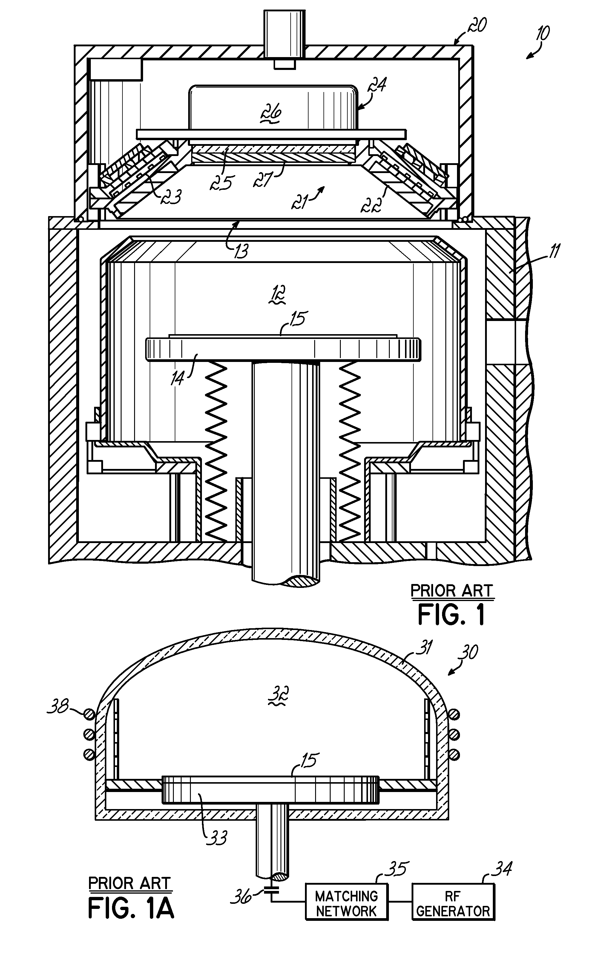
[0037] The ICP source of the present invention can be used in various plasma processing systems, such as those for performing sputter etching and deposition processes, plasma-enhanced CVD (PECVD) processes, ionized PVD (iPVD) processes, and reactive ion etching processes (RIE). FIG. 1 illustrates an iPVD apparatus 10 of a type for the manufacture of semiconductor wafers in which embodiments of the invention are described below. Examples of semiconductor wafer processing machines of the iPVD type are described in U.S. Pat. Nos. 6,080,287 and 6,287,435, both hereby expressly incorporated by reference herein.

[0038] The iPVD apparatus 10 includes a vacuum processing chamber 12 enclosed in a chamber wall 1 having an opening 13 at the top thereof in which is mounted an ionized sputtering material source 20, which seals the opening 13 to isolate the vacuum within the chamber 12 from external ambient atmosphere. Within the chamber 12 is a wafer support 14 that holds a semiconductor wafer 1...


PUM

PropertyMeasurementUnit
diametersaaaaaaaaaa
diametersaaaaaaaaaa
Pressuresaaaaaaaaaa

Abstract

An inductively coupled plasma source is provided with a peripheral ionization source for producing a high-density plasma in a vacuum chamber for semiconductor wafer coating or etching The source has a segmented configuration with high and low radiation segments and produces a generally ring-shaped array of energy concentrations in the plasma around the periphery of the chamber. Energy is coupled from a segmented low inductance antenna through a dielectric window or array of windows and through a segmented shield or baffle. The antenna for the source is a planer coil having at least two windings with the gap between the windings variable or modulated to control the antenna inductance around the antenna. The antenna has a plurality of, for example three, high inductance segments as a result of the conductor windings being closely spaced alternating with low inductance segments as a result of the conductor windings being widely spaced. The antenna and a shield are part of a plasma source. The shield has a plurality of high transparency segments aligning with the high inductance segments of the antenna. The shield may also have one or more additional high transparency segments along the low inductance portions of the antenna enhance formation of a plasma ring in the chamber.

Description

[0001] This application is a Continuation-In-Part and Divisional of U.S. patent application Ser. No. 10 / 717,268, filed by applicant on Nov. 19, 2003, hereby expressly incorporated herein by reference.[0002] This application is also related to U.S. patent application Ser. No. 11 / 278,263, filed on Mar. 31, 2006, hereby expressly incorporated by reference herein. [0003] 1. Field of the Invention [0004] This invention relates to high-density plasma generating devices, systems and processes for the manufacture of semiconductor wafers. In particular, the invention relates to antenna structure for producing high-density inductively coupled plasmas (ICP) for such systems and processes. [0005] 2. Background of the Invention [0006] In a variety of integrated circuit (IC) fabrication processes, including plasma etching, plasma enhanced chemical vapor deposition (PECVD), and plasma sputter deposition applications, plasmas are produced within a process chamber by introducing a process gas at vac...

Claims


Application Information

Patent Timeline
Patent Type & Authority Applications(United States)
IPC IPC(8): C23C16/00H01J37/32
CPCH01J37/321H01J37/3211C23C14/358H01J37/32431
Inventor BRCKA, JOZEF
Owner TOKYO ELECTRON LTD
Why Eureka
Try Eureka