Floor for an aircraft cargo compartment and method for the assembly thereof

Active Publication Date: 2006-10-19
TELAIR INTERNATIONAL GMBH
View PDF15 Cites 41 Cited by
  • Summary
  • Abstract
  • Description
  • Claims
  • Application Information

AI Technical Summary

Benefits of technology

[0006] It is the objective of the invention to disclose a cargo-compartment floor as well as a method for its ass

Problems solved by technology

Furthermore, sites below the floor elements are made accessible that could not be reached at all in the cas

Method used


Image

  • Floor for an aircraft cargo compartment and method for the assembly thereof
  • Floor for an aircraft cargo compartment and method for the assembly thereof
  • Floor for an aircraft cargo compartment and method for the assembly thereof

Examples


Example

[0038] In the following description, the same reference numerals are used for identical parts or parts with identical actions.

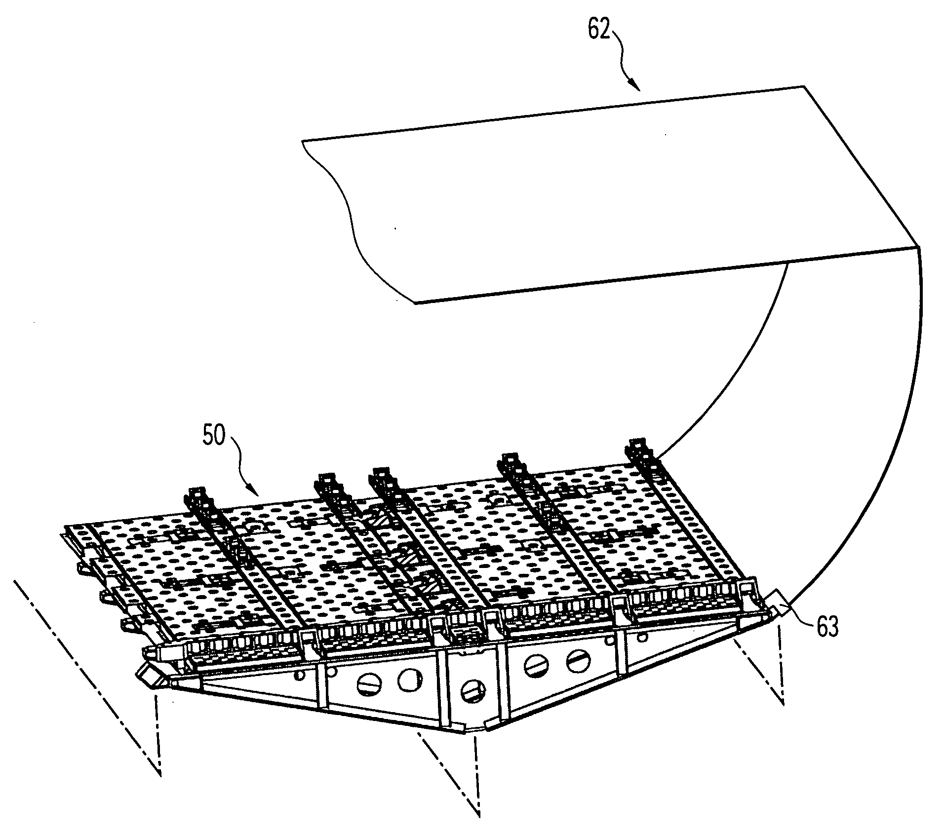
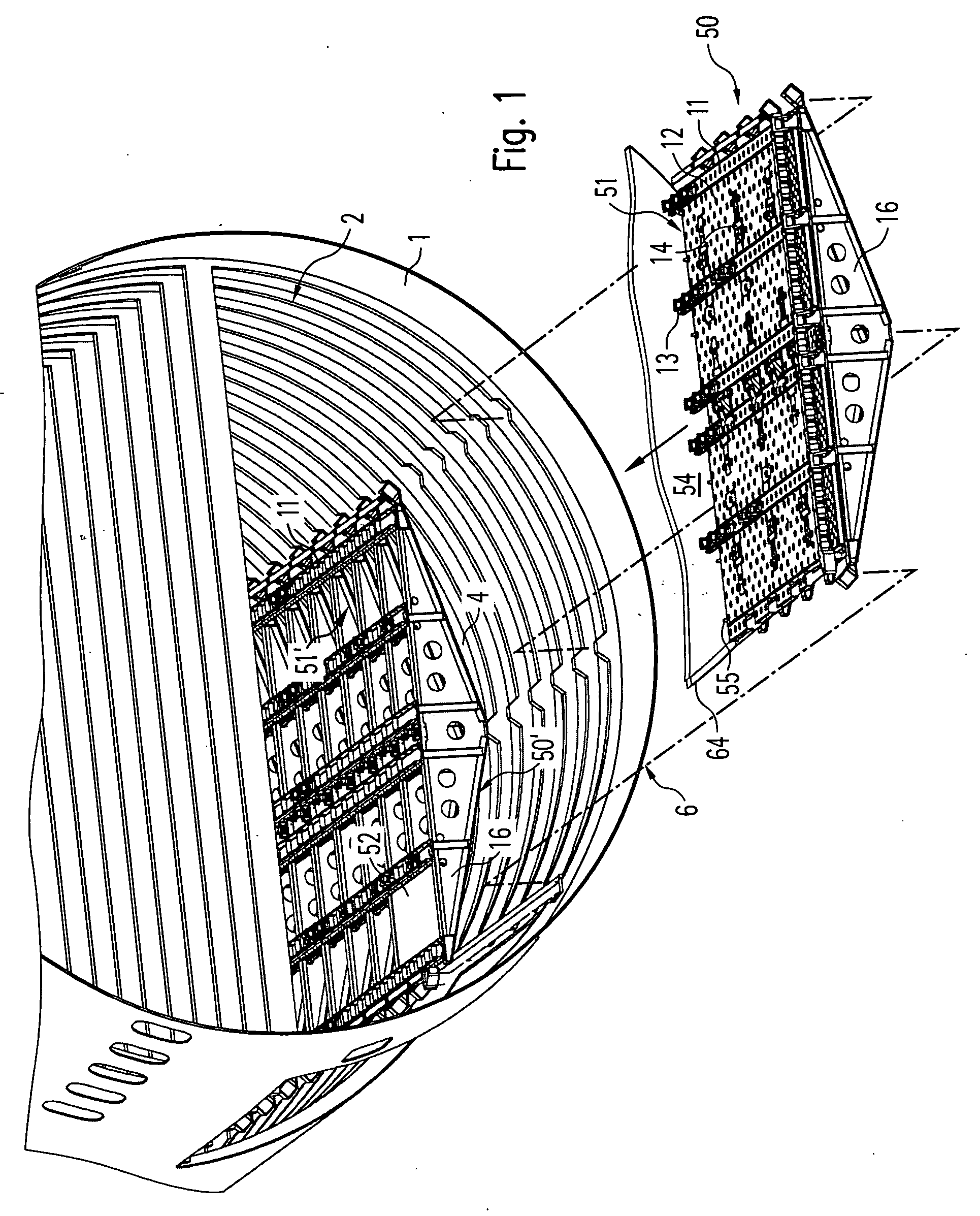
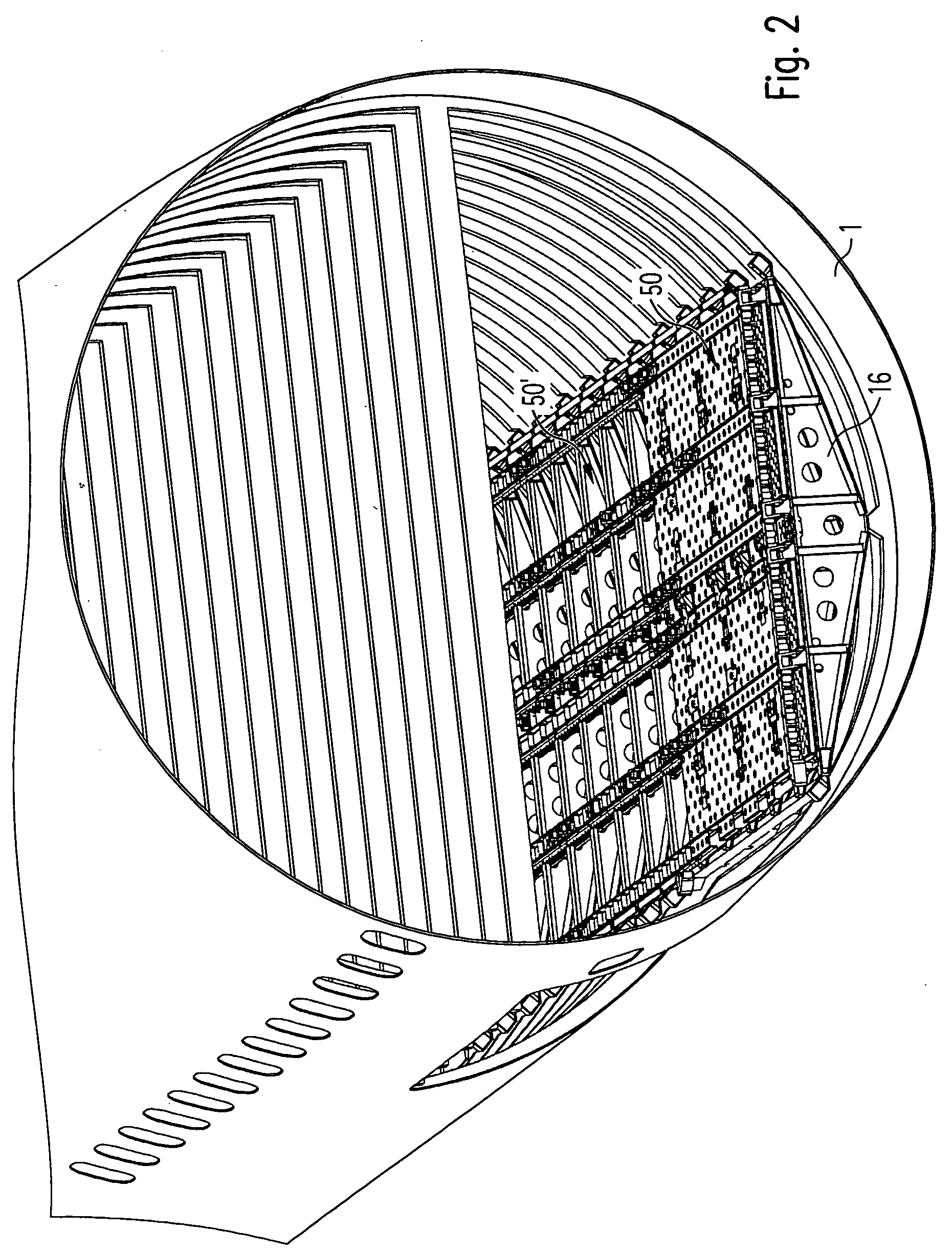
[0039] As shown in FIG. 1, a body or an (outer) skin 1 of an aircraft encloses in the lower half 6 of the fuselage a cargo compartment 2, in which floor elements 51 form a cargo-compartment floor, below which is a bilge space 4. The floor elements 51 are fixed to supporting elements, so-called floor beams 16, which in turn are fixed to the skin 1 of the aircraft.

[0040] On or at the floor elements 51 there are attached surfaces on which to walk, called floorboards, as well as functional units for transporting and securing loads, namely roller elements 11, ball elements 12, latches 13 and roller-drive units, so-called PDUs 14, as is known from the printed documents cited at the outset.

[0041] The floor elements 51 for producing the cargo-compartment floor are attached to the floor beams 16 while outside the aircraft, so as to produce floor modules 50 that wil...


PUM

PropertyMeasurementUnit
Electrical resistanceaaaaaaaaaa

Abstract

In conventional aircraft cargo compartments panels or similar flat floor elements are fastened to floor beams or similar supporting elements that are installed in the body of the aircraft. Subsequently functional units such as roller elements latches or PDUs are mounted and connected to one another by way of appropriate control conductors. In the present invention it is proposed to fasten the floor elements permanently to the supporting beams so as to form prefabricated floor modules and to install these floor modules in the aircraft.

Description

RELATED U.S. APPLICATIONS [0001] Not applicable. STATEMENT REGARDING FEDERALLY SPONSORED RESEARCH OR DEVELOPMENT [0002] Not applicable. REFERENCE TO MICROFICHE APPENDIX [0003] Not applicable. FIELD OF THE INVENTION [0004] The invention relates to a floor for an aircraft cargo compartment as well as to a method of assembling said floor. BACKGROUND OF THE INVENTION [0005] From the documents DE 19627846A1 (U.S. Pat. No. 5,927,650), DE 19720224A1 (U.S. Pat. No. 6,125,984), EP 0649802A1, U.S. Pat. No. 4,807,735 or U.S. Pat. No. 3,612,316 floors for aircraft cargo compartments are known in which panels or similar flat floor elements are provided for the fixation of roller elements, ball elements, latches, PDUs or similar functional units; these panels are mounted on a flat floor of an aircraft or on floor beams or similar supporting elements that support the panels and are themselves connected to a body or skin of the aircraft. In order to assemble the known cargo-compartment floors, init...

Claims


Application Information

Patent Timeline
IPC IPC(8): B64C1/00B64C1/06B64C1/20B64C1/22B64D9/00B64D11/02
CPCB64C1/061B64C1/064B64C1/065B64C1/068B64C1/20Y10T29/49826B64D9/00B64D11/02B64D2011/0046B64C1/18B64C1/22B64C2211/00
Inventor HUBER, THOMASPATZLSPERGER, ANDREASHOLZNER, RICHARD
Owner TELAIR INTERNATIONAL GMBH
Why Eureka
Try Eureka