
Device with a suction cup for supporting and mounting articles to a surface

a technology of fixing device and suction cup, which is applied in the direction of machine supports, lighting and heating equipment, and support devices for lighting and heating, etc., can solve the problems of affecting aesthetics, even altering the surface, and the suction cup cannot be attached on a very flat and smooth surfa

Inactive Publication Date: 2006-10-19
NANJING CHERVON IND
View PDF6 Cites 18 Cited by
  • Summary
  • Abstract
  • Description
  • Claims
  • Application Information

AI Technical Summary

Benefits of technology

[0011] With these configurations, the fixing device of the present invention can be fixed on a smooth or even less smooth surface for a long time, and / or can be easily and quickly taken down from the surface, and / or provides for energy-savings while being fixed on a surface. In addition, the fixing device of the invention can be used to support articles of different shapes and functions.

Problems solved by technology

However, adhesive and glue are apt to foul the attached surface, and nails are liable to leave holes in the wall, which influences aesthetics and even alters the surface.
Generally, such a suction cup can only be attached on a very flat and smooth surface such as glass, glazed tile and the like, and can only carry a very small load.
If a suction cup of this type carries a heavier load than it can afford or is attached on a surface which is not very smooth, air will influx into the chamber defined by the skirt portion and the surface and the device will not adhere to the desired surface.
On the other hand, if a suction cup has a very strong suction force, a new problem will occur, that is, it will be very difficult to remove from the wall surface on which it has been fixed.

Method used


Image

  • Device with a suction cup for supporting and mounting articles to a surface
  • Device with a suction cup for supporting and mounting articles to a surface
  • Device with a suction cup for supporting and mounting articles to a surface

Examples


Embodiment Construction

[0025] While this invention is susceptible of embodiments in many different forms, there is shown in the drawings and will herein be described in detail preferred embodiments of the invention with the understanding that the present disclosure is to be considered as an exemplification of the principles of the invention and is not intended to limit the broad aspect of the invention to the embodiments illustrated.

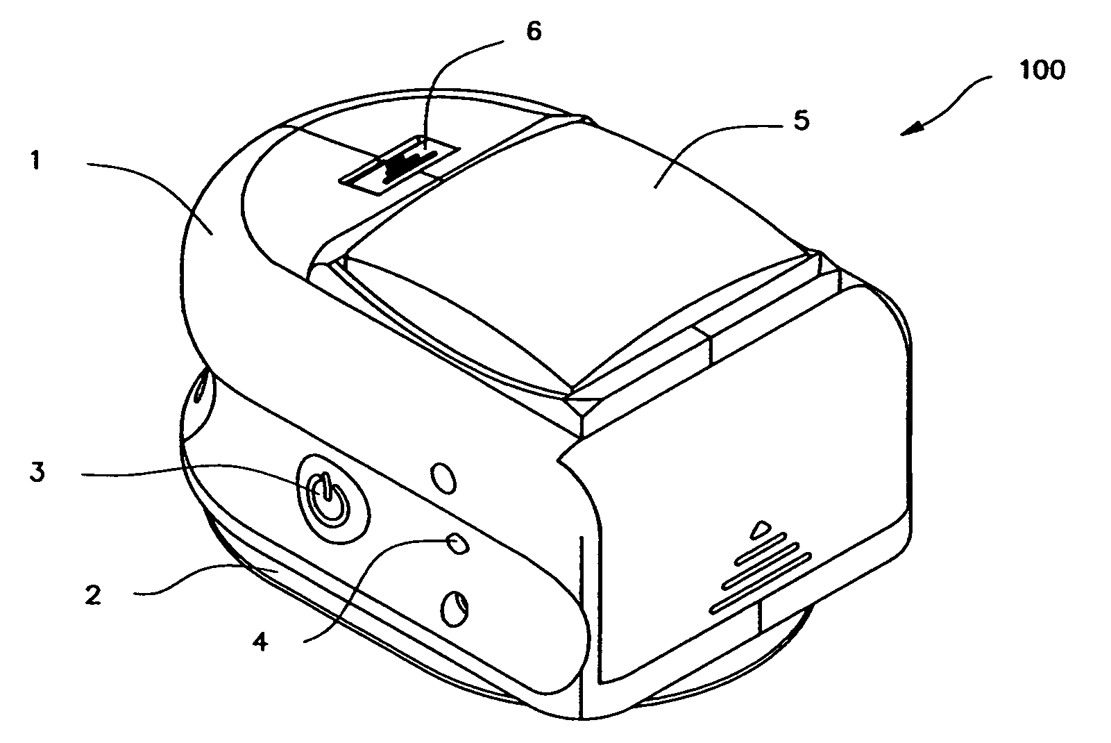
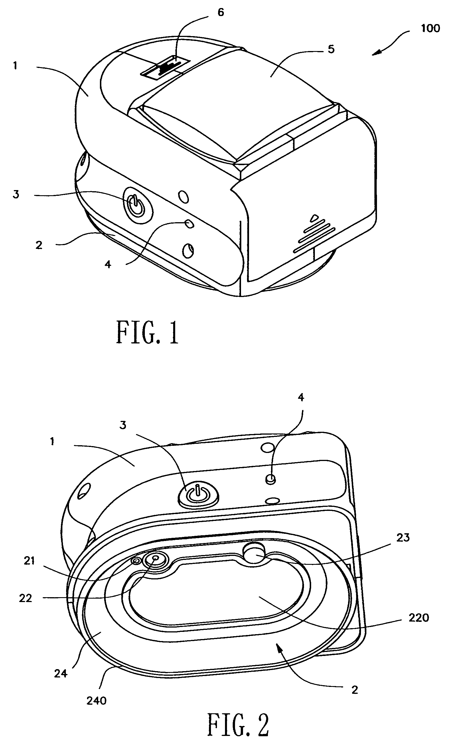
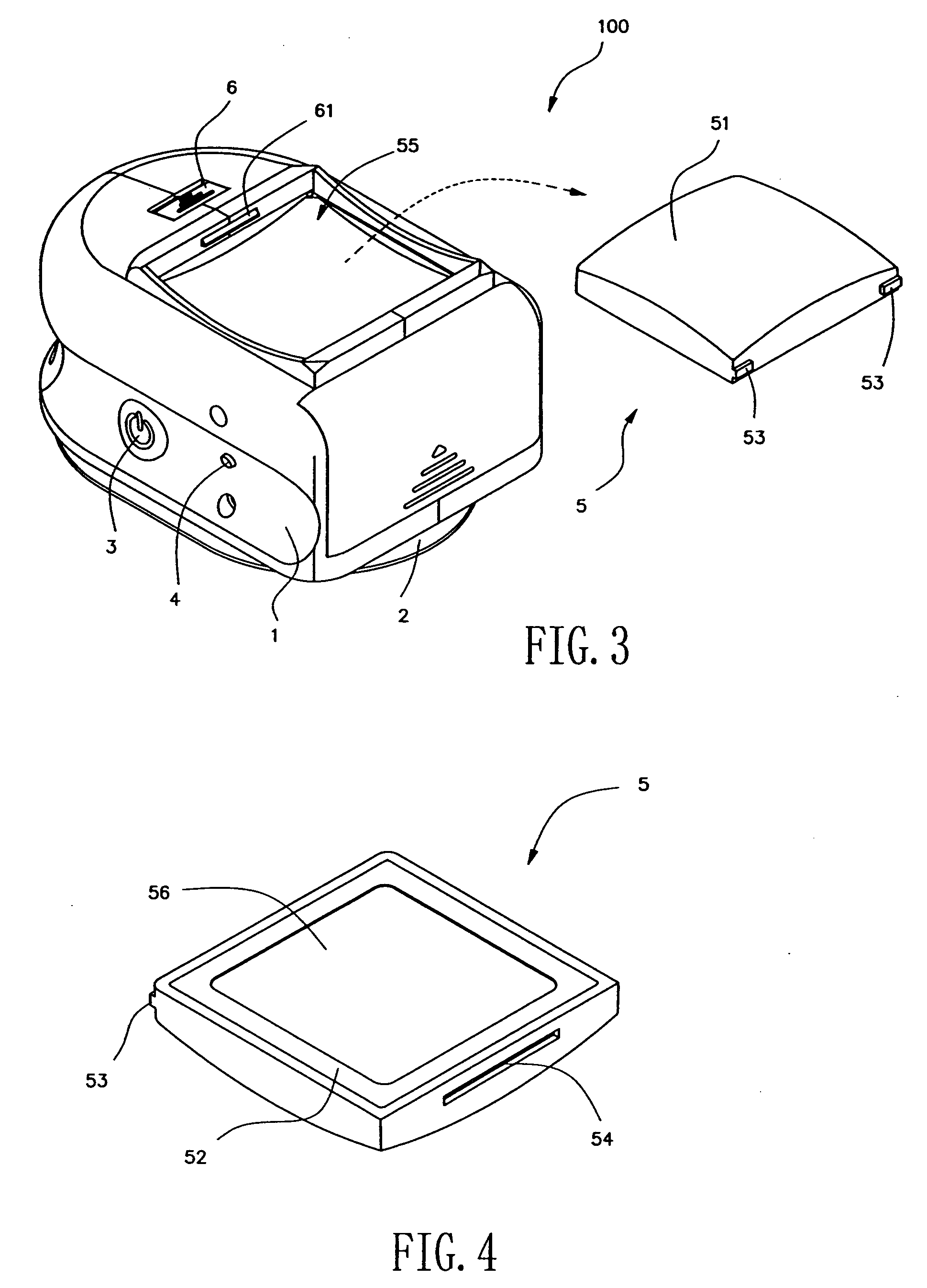
[0026] Referring to FIGS. 1, 2, 5 and 6, a fixing device 100 comprises a housing 1, a suction cup 2, and a mini-sized vacuum pump 9 contained in the housing 1. The pump 9 is connected to an air outlet 22 on the top 220 of the suction cup 2 via a conduit 82. On the housing 1, a power switch 3 is provided, which could be turned on to connect a battery pack 7 to a circuit. In this manner, the vacuum pump 9 is powered on and starts to operate. As a result, the air under the suction cup 2 is thus exhausted out through the pipe 82 from the air outlet 22.

[0027] Referring to FIG. 2,...


PUM


Abstract

A fixing device with a suction cup for supporting and mounting articles to a surface is provided by the present invention. The fixing device comprises a housing, a suction cup assembly and an air outlet formed in the suction cup assembly. A vacuum pump is contained in the housing and is connected to the air outlet via a first conduit. A battery pack supplies power to the vacuum pump and a switch is provided for activating the vacuum pump. The fixing device can further include a valve for releasing the device from the attached surface, an actuating member for automatically activating the vacuum pump, and a fixing pad with a magnet and two different-shaped surfaces. Accordingly, the fixing device can be fixed on a smooth or roughened surface for a long time and can be easily and quickly removed without damaging the surface. In addition, the fixing device can also be used to support and mount articles of different shapes and functions to the wall.

Description

CROSS-REFERENCE TO RELATED APPLICATIONS [0001] This application claims priority to Chinese Application No. 200520068932.6, filed on Feb. 4, 2005. FEDERALLY SPONSORED RESEARCH OR DEVELOPMENT [0002] None. TECHNICAL FIELD [0003] The present invention relates to a fixing device with a suction cup capable of being attached to a surface, for fixing an article which is connected to the fixing device on the surface. BACKGROUND OF THE INVENTION [0004] It is well known in the art that adhesive, glue, nails or suction cups can be used to fix articles on a vertical or inclined surface. However, adhesive and glue are apt to foul the attached surface, and nails are liable to leave holes in the wall, which influences aesthetics and even alters the surface. A suction cup, however, does not have the above drawbacks. [0005] In prior fixing devices utilizing suction cups, a suction member having a skirt portion, which is usually made of rubber or plastics, is flattened on a surface. A chamber is defin...

Claims


Application Information

Patent Timeline
IPC IPC(8): A45D42/14
CPCF16B47/00F21V21/092
Inventor LIU, YI
Owner NANJING CHERVON IND
Learn More