
Vacuum sealable bag apparatus and method

a vacuum sealable bag and apparatus technology, applied in the field of vacuum sealable storage bags, can solve the problems of non-vacuum sealable bags, non-vacuum sealable bags, and high cost and achieve the effect of avoiding the purchase of vacuum sealable bags or abandoning vacuum sealing altogether, and avoiding the use of vacuum sealable bags

Inactive Publication Date: 2006-01-31
FOODFRESH TECH
View PDF42 Cites 60 Cited by
  • Summary
  • Abstract
  • Description
  • Claims
  • Application Information

AI Technical Summary

Benefits of technology

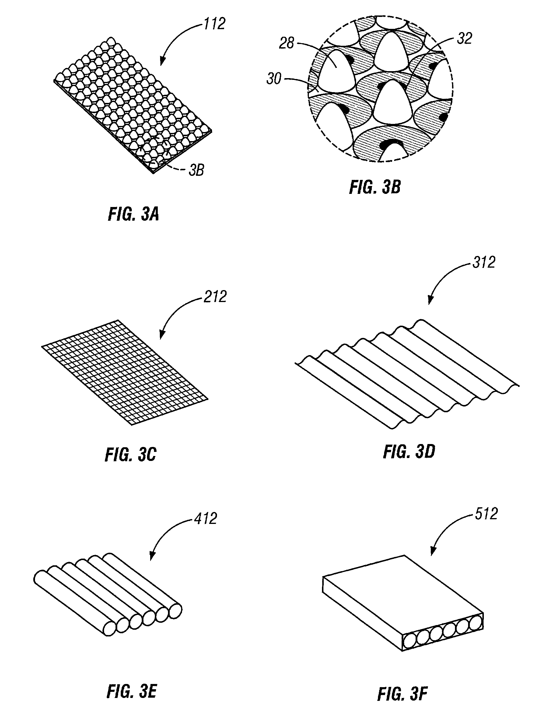
[0011]The venting strip can also or instead be tack welded (e.g., heat staked) at any point along its length and at any location within the storage bag. For example, one end of the venting strip can be secured to an interior wall of the storage bag adjacent to the mouth of the storage bag. Securing the venting strip in any of the manners described above will help maintain the venting strip's position in the storage bag while the storage bag is being loaded.

Problems solved by technology

Vacuum sealable bags that are shaped to better facilitate evacuation as described above are typically much more expensive than equivalent, non-vacuum sealable bags because of the increased material costs and special manufacturing processes needed to create such bags.
As a result, the consumer may decide against purchasing vacuum sealable bags or abandon vacuum sealing altogether.
This fixed sealing time may not always be appropriate for different types of vacuum sealable bags.
Insufficient sealing times may then lead to a leaking vacuum seal.
Fully evacuating the bags is also difficult to accomplish both with a conventional bag and a vacuum sealable bag.
This results when pockets of air no longer have an exit channel from the bag upon sealing.
This is also a problem with some vacuum sealable bags.
It is not uncommon for either embossed or ribbed walls of a vacuum sealable bag to collapse before complete evacuation has occurred, thereby trapping isolated pockets of air within the bag upon sealing.

Method used


Image

  • Vacuum sealable bag apparatus and method
  • Vacuum sealable bag apparatus and method
  • Vacuum sealable bag apparatus and method

Examples


Embodiment Construction

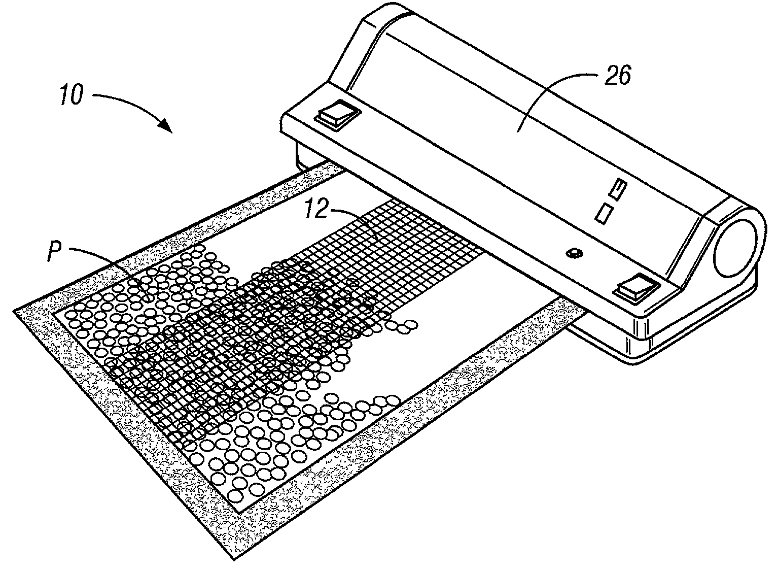
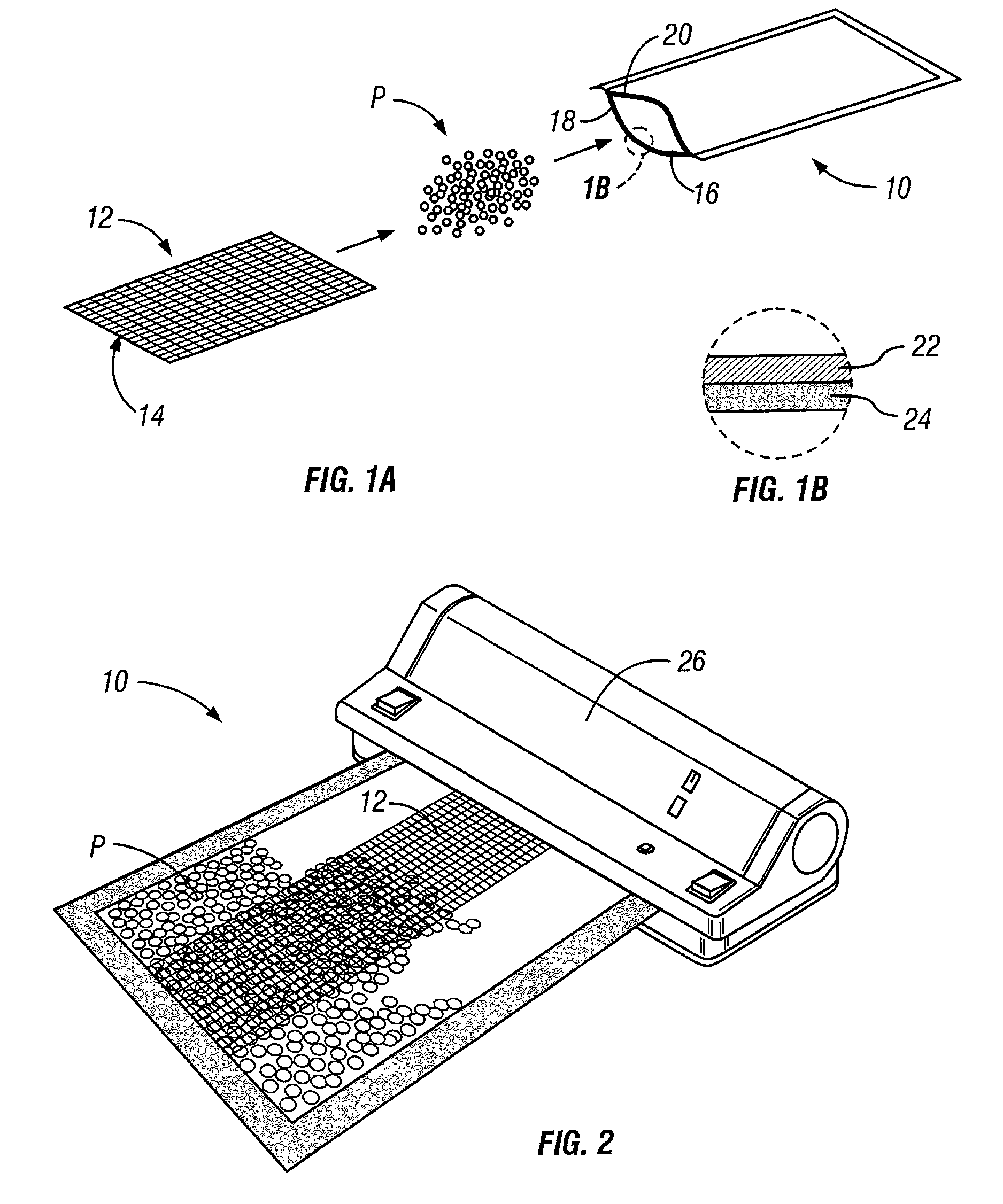
[0032]With reference first to FIG. 1a, a vacuum sealable bag 10 is shown with an unattached venting strip 12. The unattached venting strip 12 can be inserted within the bag 10 prior to, after, or during insertion of product P to be stored within the bag 10. Preferably, the unattached venting strip 12 is placed within the bag 10 such that an end 14 of the strip 12 extends to a point flush with the bag edges defining the mouth or open end 16 of the bag 10, although the venting strip 12 can instead extend outside of the open end 16 of the bag 10 or can be slightly recessed from the open end 16 of the bag 10. The bag 10 includes two pieces or “panels” of sheet material 18, 20 that are sealed together along the side and bottom edges of the bag 10. In the illustrated preferred embodiment shown in FIG. 1b, each piece of sheet material 18, 20 consists of a heat sealable inner layer 22 and a high barrier material outer layer 24 resistant to gas permeation as is best shown in FIG. 1b. The inn...


PUM

PropertyMeasurementUnit
Heataaaaaaaaaa
Permeation propertiesaaaaaaaaaa

Abstract

In some embodiments of the present invention, a strip of material is employed to assist in evacuating a storage bag. Although this venting strip can be used in vacuum sealing any type of plastic bag, in some preferred embodiments the venting strip is used in vacuum sealing storage bags having one or more heat sealable inner layers and one or more outer layers resistant to gas permeation. The venting strip can be apertured and / or can have a textured or rough surface that creates channels between the inside surface of the storage bag and the venting strip, thereby allowing air to exit from the interior of the storage bag. The venting strip can be made at least partially of heat-sealable material, and can melt with heat sealable inner layers of the storage bag when a vacuum sealer applies heat to seal the storage bag.

Description

[0001]This application claims the benefit of Provisional Application No. 60 / 284,690, filed Apr 17, 2001.FIELD OF THE INVENTION[0002]This invention relates generally to storage bags, and more particularly to vacuum sealed storage bags.BACKGROUND OF THE INVENTION[0003]Vacuum sealable bags are popular for purposes of packaging and storing all types of objects and matter. Typically, vacuum sealable bags include two opposing sheets of plastic material, each sheet having an inner layer of heat-sealable material such as polyethylene, and an outer layer of a material resistant to gas permeation (known in the food storage bag and in other storage bag industries as “high barrier” material) such as nylon or polyester. The inner layer of vacuum sealable bags are often shaped to assist in evacuating such bags. For example, some vacuum-sealable bags having embossed or ribbed inner layers defining air channels extending to the mouth of the bag. These channels provide passages for air to exit the b...

Claims


Application Information

Patent Timeline
IPC IPC(8): B65D81/20
CPCB65B31/047B65D81/264B65D81/203B65D81/2023
Inventor SHANNON, DANIEL P.SHANNON, CINDY PATRICIA
Owner FOODFRESH TECH
Learn More