Eureka AIR delivers breakthrough ideas for toughest innovation challenges, trusted by R&D personnel around the world.

Golf club head and surface finishing tool and method for forming pattern thereon

a golf club head and surface finishing technology, which is applied in the field of surface finishing tools and a fabricating method of golf club heads, can solve the problems of limited position of conventional patterns, limited application of planar milling, and limited lifetime and reliability of machine tools

Inactive Publication Date: 2007-06-14
FUSHENG IND CO LTD
View PDF5 Cites 59 Cited by
  • Summary
  • Abstract
  • Description
  • Claims
  • Application Information

AI Technical Summary

Benefits of technology

[0007] Accordingly, the purpose of the present invention is to provide a widely used surface finishing tool for forming patterns on any preferred region of the golf club in addition to the planar surface.
[0008] The purpose of the present invention is to provide a fabricating method having simple process and lower cost by using the surface finishing tool mentioned above.
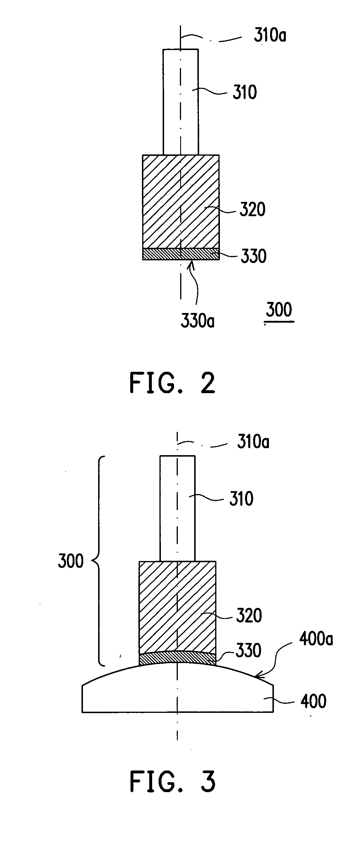
[0017] With the elasticity of the resilient cylinder, it is assured that the rough surface of the rubbing head is kept contacting with the golf club head during the fabricating process, and thus the pattern can be formed on any preferred regions of the golf club head, even the one having curved surface.

Problems solved by technology

However, the conventional fabricating method for forming the patterns on the golf club head still has at least the following limitation and drawbacks.
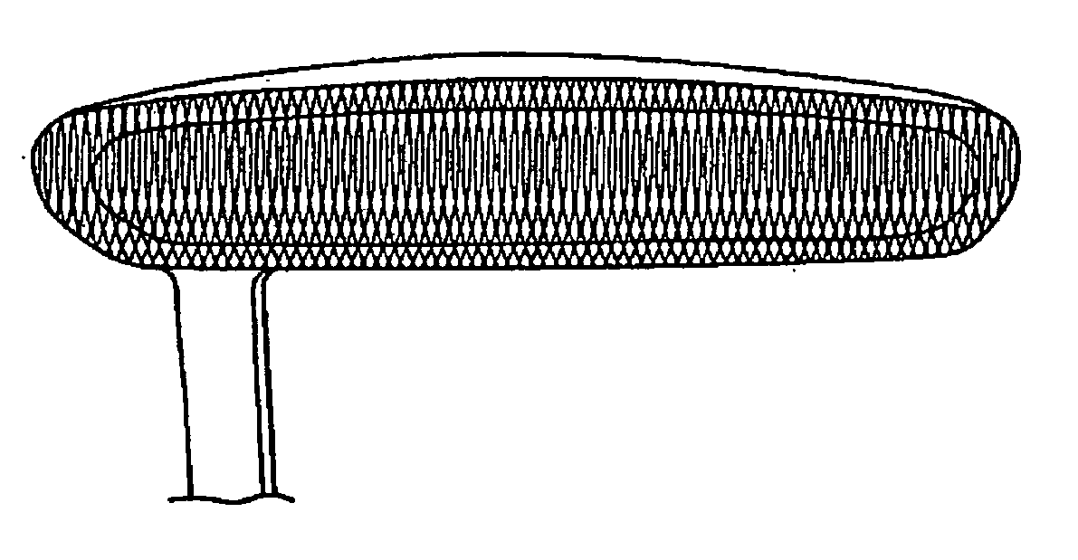
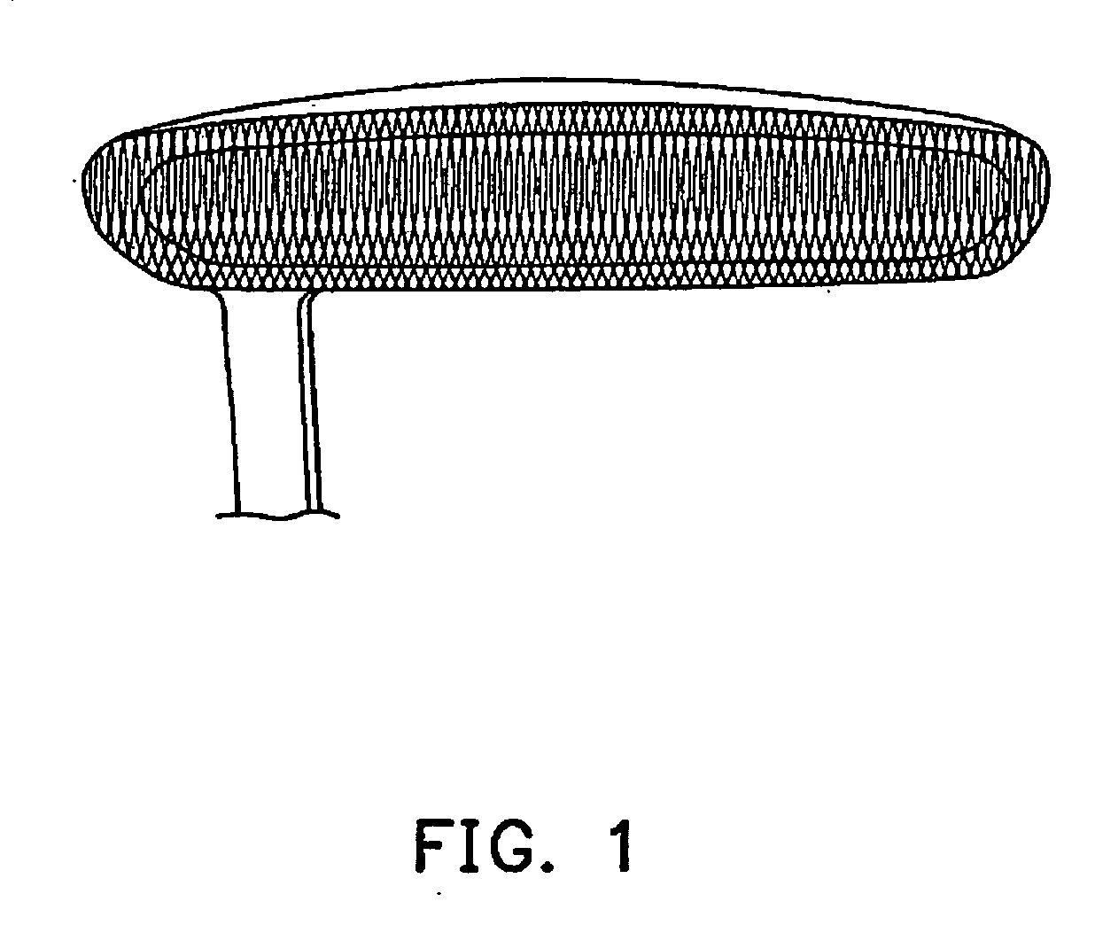
Firstly, the planar milling can be only applied on a planer surface, and thus the positions of the conventional patterns are limited on specific regions of the golf club, e.g. the striking surface of the putter.
Secondly, application of the planar milling is restricted by the lifetime and the reliability of the machine tool, wherein high hardness or toughness material are excluded from being fabricated.
Furthermore, the fabricating process of the planar milling performed by the NC machine is complex and takes a long time, which leads to a high production cost.

Method used


Image

  • Golf club head and surface finishing tool and method for forming pattern thereon
  • Golf club head and surface finishing tool and method for forming pattern thereon
  • Golf club head and surface finishing tool and method for forming pattern thereon

Examples


Embodiment Construction

[0023] Reference will now be made in detail to the present preferred embodiments of the invention, examples of which are illustrated in the accompanying drawings. Wherever possible, the same reference numbers are used in the drawings and the description to refer to the same or like parts.

[0024] The present invention mainly provides a surface finishing tool and a fabricating method applying the same for forming a pattern on a golf club head. By the surface finishing tool and the fabricating method, the pattern can be easily formed even on a curved surface of the golf club head in a simpler and low-cost way. The surface finishing tool and the accompanying fabricating method will now be illustrated in more detailed by embodiments in the following paragraphs, wherein a work piece for being fabricated in the embodiments can be various portion of the golf club head, such as crown, sole, striking surface, or back surface.

[0025]FIG. 2 schematically shows a surface finishing tool according...


PUM


Abstract

A surface finishing tool and a fabricating method for forming a pattern on a golf club head are provided. The surface finishing tool comprises a shank, a resilient cylinder, and a rubbing head. The shank has a center axis, and the resilient cylinder is disposed along the center axis and fixed on an end of the shank. The rubbing head has a rough surface and is disposed on the resilient cylinder. The fabricating method applies the surface finishing tool to form the pattern on the golf club head, wherein the surface finishing tool is driven to rotate along the center axis first. Then, the surface finishing tool is moved for keeping the rough surface of the rubbing head contacting with the golf club head, wherein the resilient cylinder is deformed along a profile of the golf club head as the rubbing head contacts with the golf club head.

Description

CROSS-REFERENCE TO RELATED APPLICATION [0001] This application claims the priority benefits of U.S. provisional application Ser. No. 60 / 749,178, filed on Dec. 19, 2005. All disclosures are incorporated herewith by reference.BACKGROUND OF THE INVENTION [0002] 1. Field of the Invention [0003] The present invention generally relates to a machine tool and a fabricating method of a golf club head. More particularly, the present invention relates to a surface finishing tool and a method for forming a pattern on a golf club head. [0004] 2. Description of Related Art [0005] Sports are becoming more and more popular, and golf has already become one of the most widely enjoyed sports. In addition, the number of participants in the sport of golf has risen rapidly. In which, the golf club used for playing golf, because of the varieties in purposes and course geographies, are categorized into different types such as wood club, iron club, and putter. However, an appearance design is also important...

Claims


Application Information

Patent Timeline
Patent Type & Authority Applications(United States)
IPC IPC(8): A63B53/00
CPCA63B53/04A63B53/0487A63B53/047A63B53/0466B24D7/18A63B60/00
Inventor LO, CHIH-WEILIN, YUAN-FU
Owner FUSHENG IND CO LTD
Why Eureka
Eureka Blog
Learn More