Rotary folder comprising a cutting device for cross-cutting at least one web

Inactive Publication Date: 2006-10-19
KOENIG & BAUER AG
View PDF6 Cites 8 Cited by
  • Summary
  • Abstract
  • Description
  • Claims
  • Application Information

AI Technical Summary

Benefits of technology

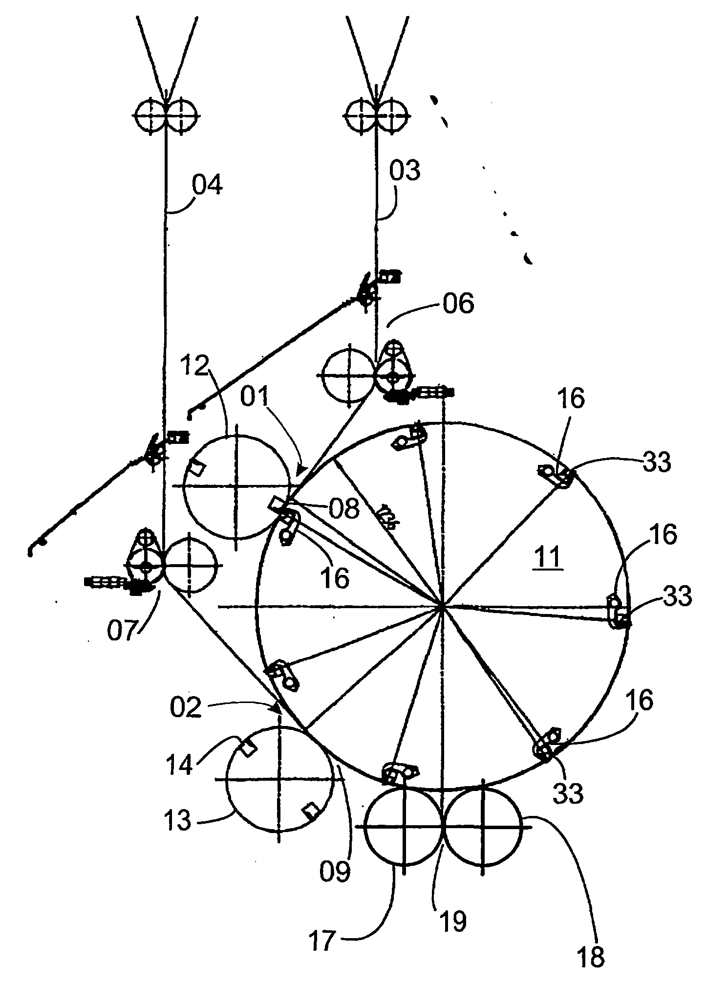
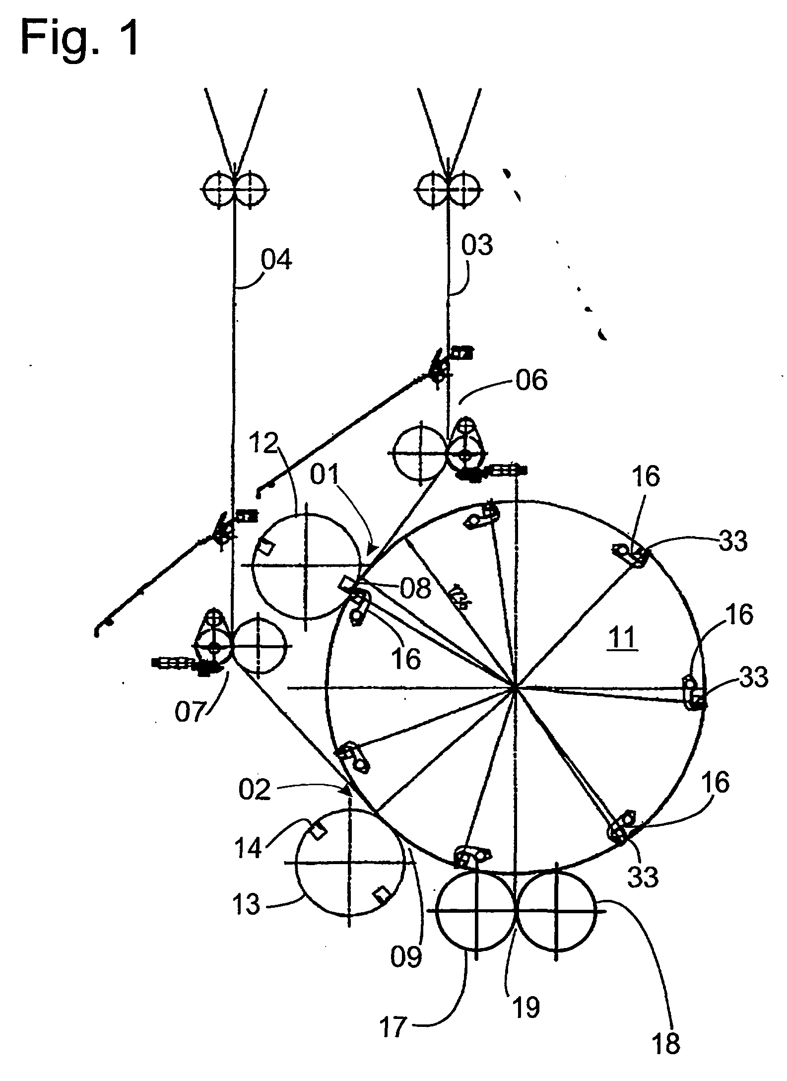
[0009] The advantages which can be obtained by the present invention lie, in particular, in that with only a small outlay for apparatus, the present invention makes possible the combining of two webs of material, which two material webs are fed to the cutting gaps on two transport carriages, into a common product. The present invention also allows the processing of a web of material, with a very large number of layers, by combining two partial webs.
[0010] Processing of webs of materials, which are composed of a large number of layers, by the use of a folding apparatus with a single cutting gap, such as is described in DE 25 17 000 C2, entails difficulties for several reasons. For one, traction rollers, which are customarily provided for use in setting a required tension in the web of material, act directly only the respectively outermost layers of the web of material. The force exerted by such traction rollers is only indirectly transmitted to the inner layers of the web of material by friction of the layers of material against each other. These frictional forces are not accurately controllable, particularly if it is necessary to guide the web around curves, such as, for example, to loop it around a roller. Therefore, the tension of the inner layers of such a web are harder to control, the greater the number

Problems solved by technology

Processing of webs of materials, which are composed of a large number of layers, by the use of a folding apparatus with a single cutting gap, such as is described in DE 25 17 000 C2, entails difficulties for several reasons.
These frictional forces are not ac

Method used


Image

  • Rotary folder comprising a cutting device for cross-cutting at least one web
  • Rotary folder comprising a cutting device for cross-cutting at least one web
  • Rotary folder comprising a cutting device for cross-cutting at least one web

Examples


Example

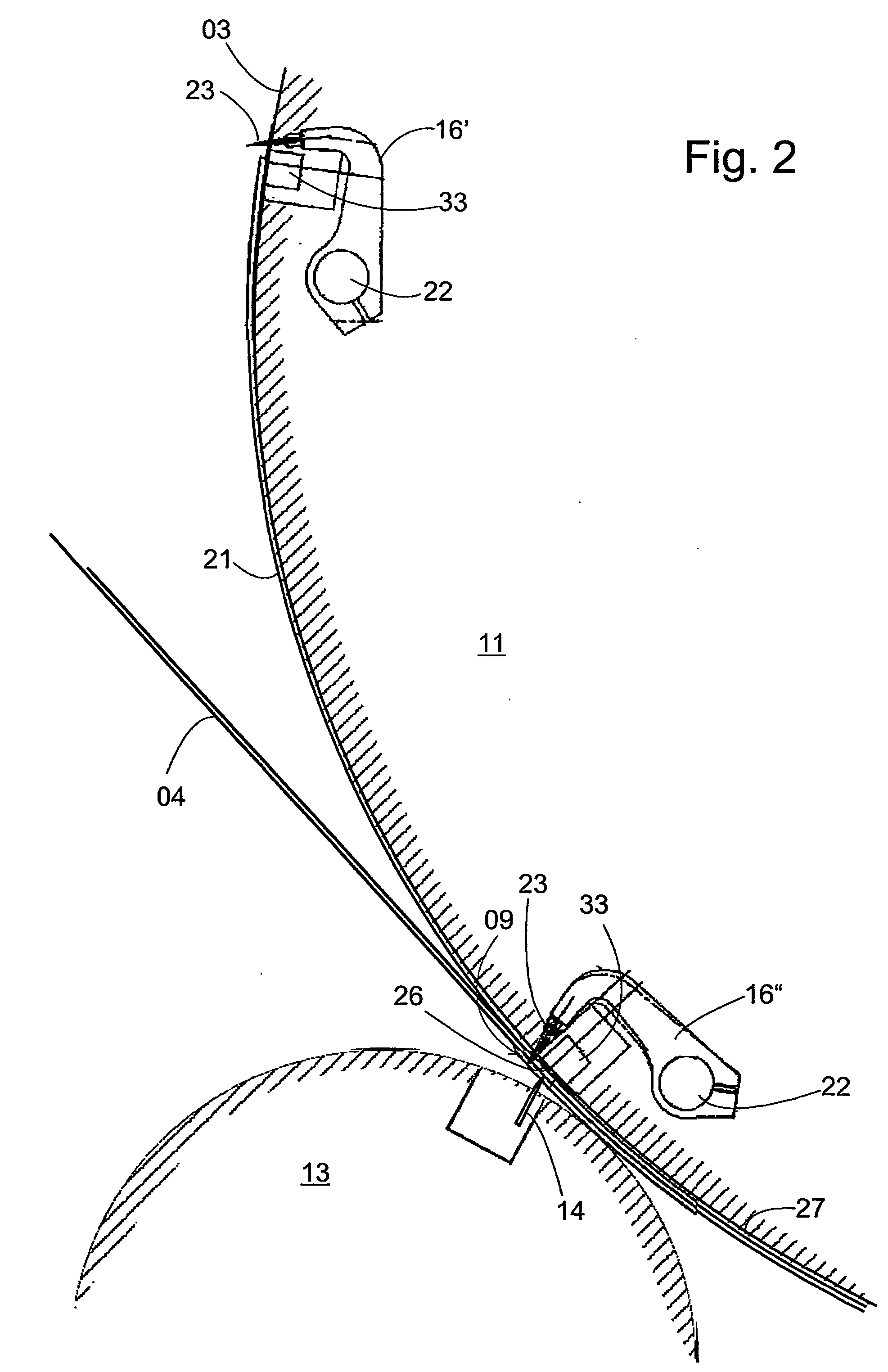
[0038] With this third embodiment, several direction changes of the movement of the spur needles 23, in the course of the revolution of the transport cylinder 11, are avoided.

Example

[0039] A fourth embodiment of the cutting device in accordance with the present invention is represented in FIG. 5, again in a partial cross-sectional view analogous to FIG. 4.

[0040] In this fourth embodiment, segments 32′, 32″ . . . , are arranged on the circumference of the transport cylinder 11 with each such segment 32′, 32′″ . . . , being located respectively between two successive spur strips 16′, 16″, 16′″, . . . , and are used for increasing the circumference of transport cylinder 11. Each one of these segments 32′, 32″ is comprised of a plurality of flexible disks, which are arranged side-by-side in the axial direction of the transport cylinder 11 and which are spaced apart by gaps. In the course of the passing of the finished cut signatures 21, 27 on to the folding rollers 17, 18, these gaps are used as the outlet openings for tines of a folding blade, which is not specifically represented. The ends of each of the disks 32′, 32′″ . . . , are anchored on head strips 31, wh...


PUM

PropertyMeasurementUnit
Lengthaaaaaaaaaa
Distanceaaaaaaaaaa
Circumferenceaaaaaaaaaa

Abstract

A rotary folder includes two cutting devices for cross-cutting at least a first web. The cutting devices are cutting or counter cylinders that can rotate together and that define gaps in conjunction with a conveying cylinder. A path of web conveyance runs through each of these gaps. The conveying cylinder or the cutting cylinders support at least one blade for cutting of a product from the webs. The conveying cylinder comprises a retaining device for retaining a cut-off signature and for conveying the signature through the respective gap. The conveying cylinder or the counter cylinders comprise thrust bearings that interact with the blade.

Description

CROSS-REFERENCE TO RELATED APPLICATIONS [0001] This patent application is the U.S. national phase, under 35 USC 371, of PCT / EP2004 / 050656, filed Apr. 30, 2004; published as WO 2004 / 096687 A1 on Nov. 11, 2004, and claiming priority to DE 103 19 774.5, filed May 2, 2003, the disclosures of which are expressly incorporated herein by reference.FIELD OF THE INVENTION [0002] The present invention is directed to a wheel folding apparatus with a cutting device for accomplishing the transverse cutting of at least one web of material. BACKGROUND OF THE INVENTION [0003] A wheel folding apparatus is typically employed, for example, to separate paper webs, which have been imprinted in a web-fed rotary printing press, into individual signatures by use of a cutting device, and to fold the individual signatures. [0004] Generally known wheel folding devices of this type usually comprise cutting devices which are provided with a transport cylinder and with a cutting cylinder, which cylinders are mutu...

Claims


Application Information

Patent Timeline
IPC IPC(8): B41F13/58B65H45/16B65H45/28
CPCB65H45/28B65H45/165
Inventor HELD, MICHAELPRUM, SEBASTIAN ALOIS
Owner KOENIG & BAUER AG
Why Eureka
Try Eureka