Networking cable tracer system

a tracer system and network cable technology, applied in the field of network cable tracer system, can solve the problems of increased service costs, increased cost, and substantial length of network cables, and achieve the effect of low cost and simple us

Active Publication Date: 2006-10-19
MERTEK INDS
View PDF15 Cites 59 Cited by
  • Summary
  • Abstract
  • Description
  • Claims
  • Application Information

AI Technical Summary

Benefits of technology

[0007] It is therefore an aspect of the instant invention to provide a network cable tracing system that is contained to the network cables, low in cost, and straightforward to use.

Problems solved by technology

The connections of each cable may be remote from one another, even being in separate rooms or spaces, and the networking cables may be of substantial length.
Tracing and identifying a remote connector section or end of a specific cable for changing its connection in a network or to facilitate replacement often is difficult, tedious and time consuming, and can lead to errors that create further service problems and additional costs.
This process may be labor intensive and expensive.
This process is also labor intensive.
As a result, these methods interfere with performance and require the workstation to be taken out of service.
If the workstation and server are located in separate rooms or in remote locations, the previous methods are labor intensive and inefficient for easy detection of termination ends.
This approach has not been widely adopted though because it requires the technician to purchase a rather limited use power pack, carry it along with all of his or her other tools and individually plug it into each networking cable as part of a test protocol.

Method used


Image

  • Networking cable tracer system
  • Networking cable tracer system
  • Networking cable tracer system

Examples


Embodiment Construction

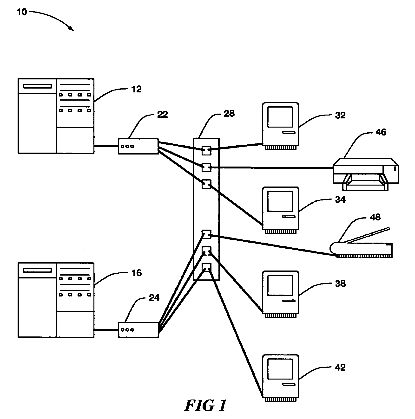
[0024]FIG. 1, shown generally by the numeral 10, illustrates, by way of background, a typical networked environment that includes servers, computers, hubs, peripheral devices, and a cable panel.

[0025] In this example computers 32, 34, 38, and 42 are each connected by networking cables to a cable panel 28. The computers can be at multiple locations. Also attached to panel 28 by networking cable are peripheral devices such as printer 46 and scanner 48. Panel 28 is often located at a central room where service personnel can access it. From panel 28 multiple computers and peripheral devices are often then linked by networked cables to hubs such as 22 and 24, which then are connected to servers such as 12 and 16. Typically, one room may house multiple servers and hubs. Various protocols are used to support data transfer between computer and server pairs. A typical protocol is Ethernet.

[0026] The example shown is a small network and typical networks are much larger. In addition to the d...


PUM


Abstract

A method and apparatus for providing a tracer function for networked cable systems used in information technology. A self contained and self powered indicator circuit is described that enables tracing the location of both ends of a networked cable without the use of external test equipment.

Description

FIELD OF THE INVENTION [0001] This invention relates to a method and apparatus for readily tracing remote connective portions of networking cables that are widely used in the information technology sector. BACKGROUND OF THE INVENTION [0002] The purpose of any networking cable is to carry data from one electronic device to another. Electronic devices include but are not limited to terminals, personal computers, printers, workstations, hubs, switches, storage devices, tape drives, routers, telephone switches, and servers. Networking cables, frequently referred to, as “jumper cables”, “patch cables”, or simply “cables”, typically are multiple pair copper wires packaged in an outer flexible sheath. Networking cables are designed to interconnect an electronic device with another electronic device. Such networking cables often are used in systems where there are many networking cables connected to frames, panels, or electronic devices, each of which may have many connecting cables and whi...

Claims


Application Information

Patent Timeline
Patent Type & Authority Applications(United States)
IPC IPC(8): G08B9/00
CPCG01R31/045G01R31/69
Inventor SCHERER, CHRISTOPHER BRIANDSHOLTIS, JONATHAN KEITH
Owner MERTEK INDS
Why Eureka
Try Eureka