Coordinate input apparatus, control method thereof, and program

Inactive Publication Date: 2006-10-19
CANON KK
View PDF41 Cites 51 Cited by
  • Summary
  • Abstract
  • Description
  • Claims
  • Application Information

AI Technical Summary

Benefits of technology

[0030] The present invention has been made to solve the above-described problems, and has as its object to provide a coordinate input apparatus capable of det

Problems solved by technology

If light shielding shadows corresponding to the two input points overlap in the light receiving unit, it is impossible to separate the light shielding shadows and detect the angle of each input point.
However, no information about the second pointer on the far side can be obtained.
However, the following problem remains unsolved.
However, if an individual characteristic such as the sensitivity of each sensor unit

Method used


Image

  • Coordinate input apparatus, control method thereof, and program
  • Coordinate input apparatus, control method thereof, and program
  • Coordinate input apparatus, control method thereof, and program

Examples


Example

First Embodiment

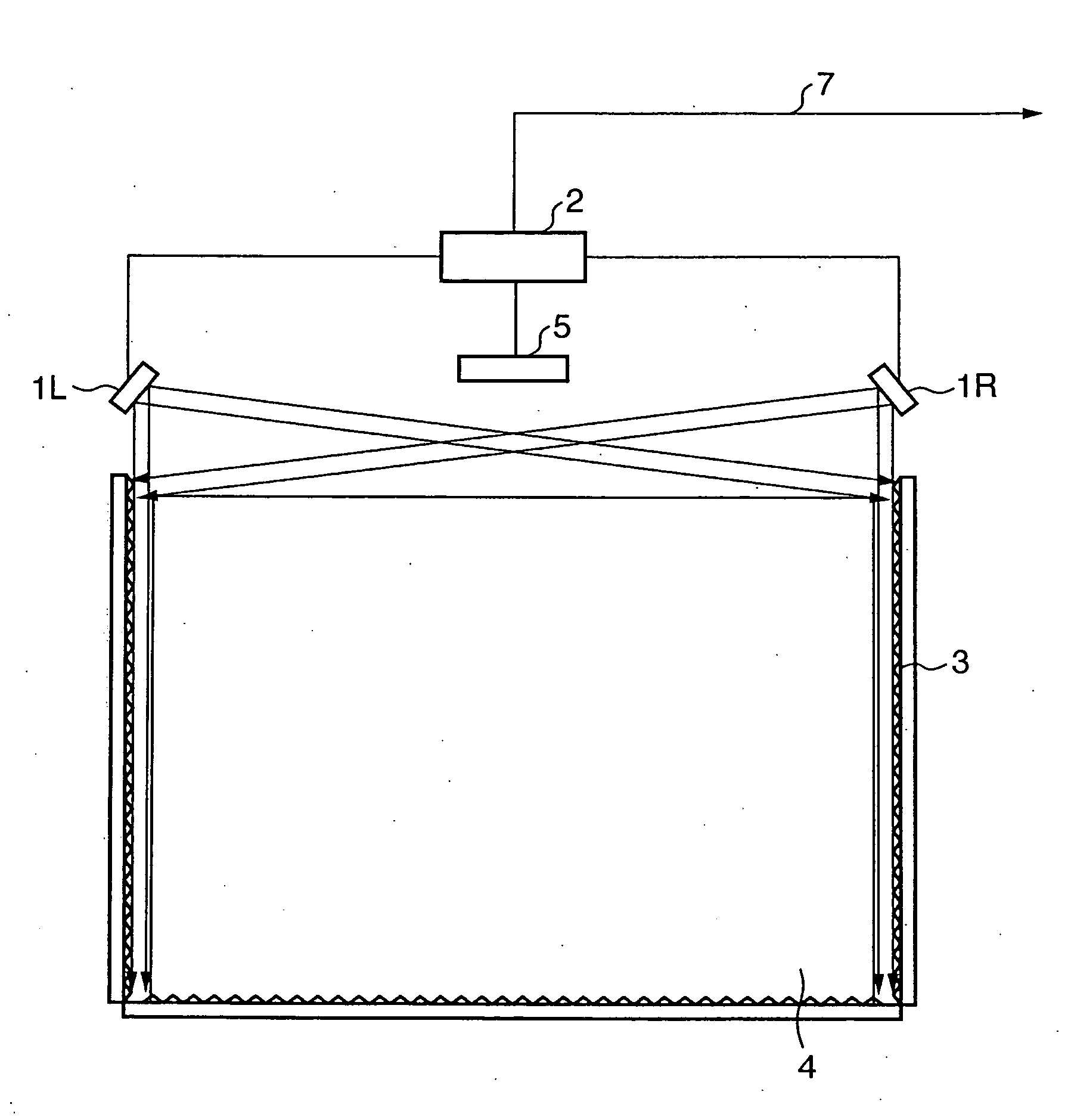
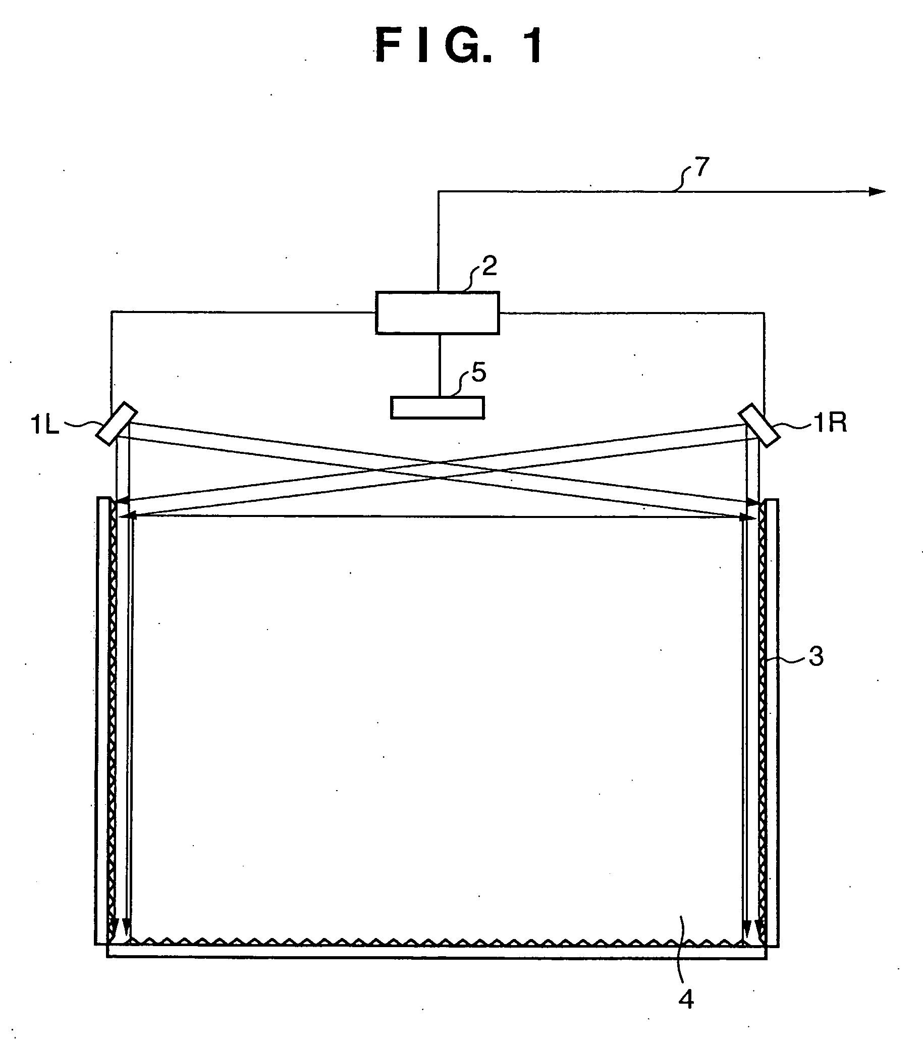
[0121] The schematic arrangement of an overall coordinate input apparatus will be described first with reference to FIG. 1.

[0122]FIG. 1 is a view showing the schematic arrangement of a coordinate input apparatus of light shielding scheme according to the first embodiment of the present invention.

[0123] Referring to FIG. 1, sensor units 1L and 1R have light projecting units and light receiving units. In the first embodiment, the sensor units 1L and 1R are arranged parallel to the X-axis of a coordinate input effective region 3 serving as a coordinate input surface and symmetrically about the Y-axis while being spaced apart by a predetermined distance, as shown in FIG. 1. The sensor units 1L and 1R are connected to a control / arithmetic unit 2. Each of the sensor units 1L and 1R receives a control signal from the control / arithmetic unit 2 and transmits a detected signal to the control / arithmetic unit 2.

[0124] A retroreflecting member 4 has a retroreflecting surface ...

Example

Second Embodiment

[0324] As described in the first embodiment, coordinate calculation can be executed by counting the number of light-shielded ranges for each sensor unit. On the other hand, as described in the “Background of the Invention”, in the input transition state, the pointer detection state changes between the sensor units so the actual number of inputs may not match the number of light-shielded ranges.

[0325] In this case, a coordinate calculation error may occur, and a wrong coordinate value may be output.

[0326] Assume a transition state wherein one input is present, and another input is being executed. Assume that a sensor unit 1L detects only one shadow although a sensor unit 1R detects two light-shielded ranges. If truth determination is executed in this state simply on the basis of the number of detected light-shielded ranges, it is determined that the sensor unit 1L detects an eclipse state while the sensor unit 1R detects a separation state.

[0327]FIG. 26 shows an ...


PUM


Abstract

A signal change range generated by a pointing operation of a pointer on a coordinate input region is specified in correspondence with the initial detection signal distribution of a detection unit in an initial state without pointing on the coordinate input region. Pieces of end information of the specified signal change range are detected. The validity of a detection state in the end information detection step is determined by using the plurality of pieces of detected end information. On the basis of the determination result, the coordinates of the point position of the pointer are calculated from the plurality of pieces of end information.

Description

FIELD OF THE INVENTION [0001] The present invention relates to a coordinate input apparatus for detecting a point position on a coordinate input region, a control method thereof, and a program. BACKGROUND OF THE INVENTION [0002] There exist coordinate input apparatuses which are used to input coordinates to a coordinate input surface by using a pointer (e.g., a dedicated input pen or finger) to control a connected computer or write characters and graphics. [0003] Conventionally, as coordinate input apparatuses of this type, touch panels of various schemes have been proposed or become commercially available. These apparatuses are widely used because a terminal such as a personal computer can easily be operated on the screen without using any special tool. [0004] There are various coordinate input schemes using, e.g., a resistive film or an ultrasonic wave. A scheme using light is disclosed in, e.g., U.S. Pat. No. 4,507,557. In U.S. Pat. No. 4,507,557, a retroreflecting sheet is provi...

Claims


Application Information

Patent Timeline
IPC IPC(8): G09G5/00
CPCG02B5/124G06F3/03545G06F3/04883G06F3/0421G06F3/0416
Inventor TANAKA, ATSUSHISATO, HAJIME
Owner CANON KK
Why Eureka
Try Eureka