Method and apparatus for measuring distance by means of radar

Active Publication Date: 2020-01-09
WRT LAB CO LTD
View PDF2 Cites 1 Cited by
  • Summary
  • Abstract
  • Description
  • Claims
  • Application Information

AI Technical Summary

Benefits of technology

[0010]According to the present invention, a feature of an obstacle through which a radar signal passes can be analyzed, a distance to a target object can be calculated by reflecting the analysis result, and thus a distance to a target object can be accurately calculated.
[

Problems solved by technology

A method of using an array antenna consumes a great deal of mon

Method used


Image

  • Method and apparatus for measuring distance by means of radar
  • Method and apparatus for measuring distance by means of radar
  • Method and apparatus for measuring distance by means of radar

Examples


Example

[0021]Since the present invention may be modified in various forms and may have various embodiments, the following exemplary embodiments are illustrated in the accompanying drawings, and are described in detail with reference to the drawings. However, this is not intended to limit the present invention to specific embodiments, and the present invention should be construed to encompass various changes, equivalents, and substitutions within the technical scope and spirit of the invention. Like numbers refer to like elements throughout in the description of each drawing.

[0022]Hereinafter, various embodiments of the present invention will be described with reference to the accompanying drawings.

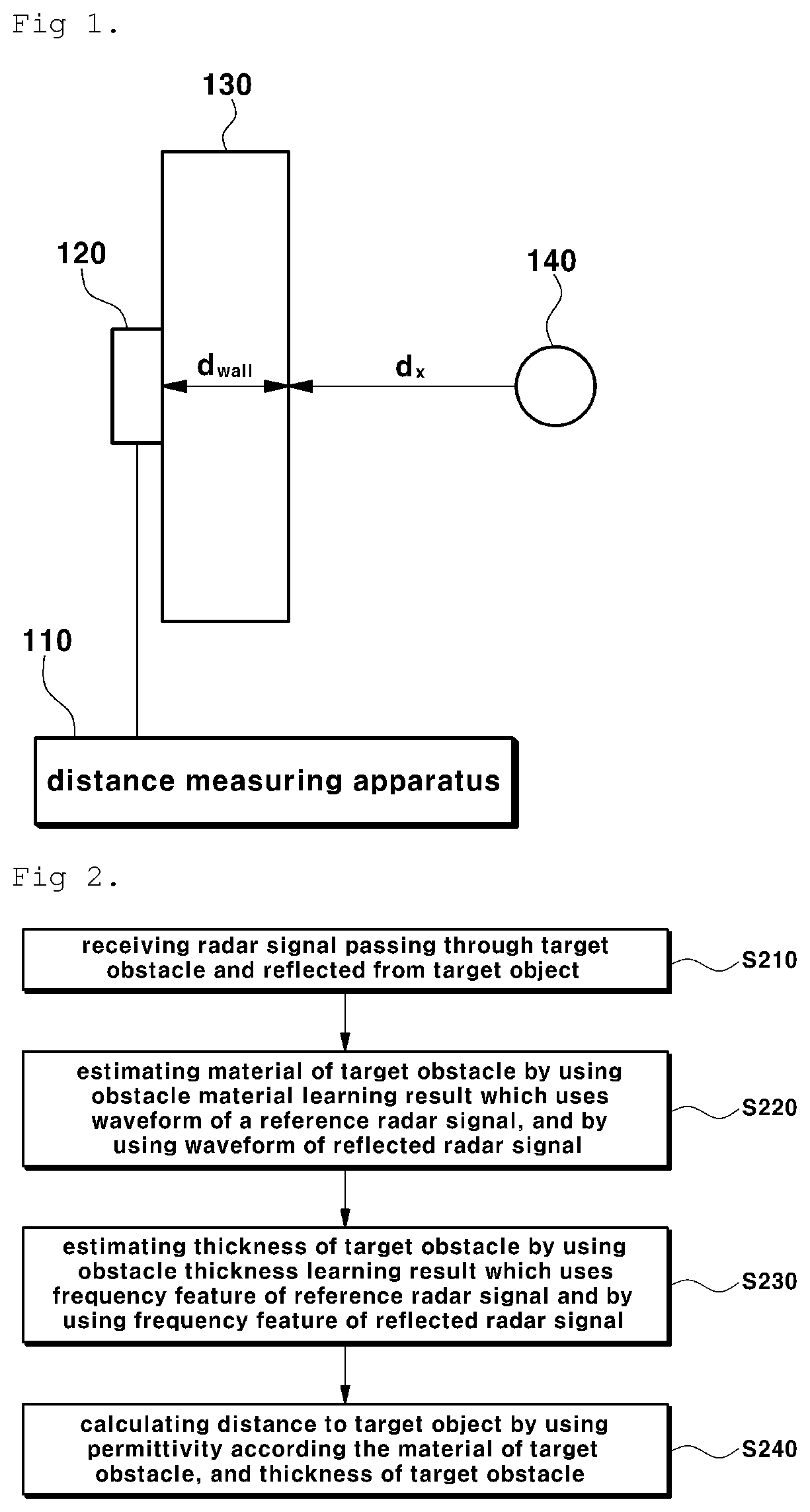
[0023]FIG. 1 is a view showing a distance measuring system using a radar according to an embodiment of the present invention.

[0024]Referring to FIG. 1, a distance measuring system according to the present invention includes a distance measuring apparatus 110 and a radar signal transmitting and re...


PUM


Abstract

Disclosed is a method and apparatus for measuring a distance to a target object by using a radar signal in an environment where an obstacle is present. The disclosed method of measuring a distance by using a radar includes: receiving a radar signal reflected from a target object by passing through a target obstacle; estimating material of the target obstacle by using an obstacle material learning result which uses a waveform of a reference radar signal, and by using a waveform of the reflected radar signal; estimating a thickness of the target obstacle by using an obstacle thickness learning result which uses a frequency feature of the reference radar signal, and by using a frequency feature of the reflected radar signal; and calculating a distance to the target object by using a permittivity according to the material of the target obstacle, and the thickness of the target obstacle.

Description

TECHNICAL FIELD[0001]The present invention relates to a method and apparatus for measuring a distance by using a radar. More particularly, the present invention relates to a method and apparatus for accurately measuring a distance in an environment where an obstacle is present.BACKGROUND ART[0002]Generally, conventional radio frequency (RF) signal based obstacle transmission studies are based on a damping ratio of received signals. The above method is a method of estimating a permittivity and a thickness of an obstacle by using an energy difference between an energy when a signal transmitted from a transmitter is received by passing through an environment where an obstacle is present, and an energy when a signal is transmitted in vacuum, and time information of how long the signal has been delayed and received is required. In addition, in the through-wall imaging field, which has been actively studied recently, an array antenna is used to overcome effects of obstacles by processing ...

Claims


Application Information

Patent Timeline
IPC IPC(8): G01S7/41G01S13/08G06N3/08G06N3/04
CPCG01S7/412G06N3/08G01S13/08G01S7/417G06N3/04G06N20/10
Inventor CHO, SUNG HOYOO, SUNG WONRYU, HAN NA
Owner WRT LAB CO LTD
Why Eureka
Try Eureka