

Optical element, measuring apparatus and measuring method
- Summary
- Abstract
- Description
- Claims
- Application Information
AI Technical Summary
Benefits of technology
Problems solved by technology
Method used
Image


Examples
Embodiment Construction
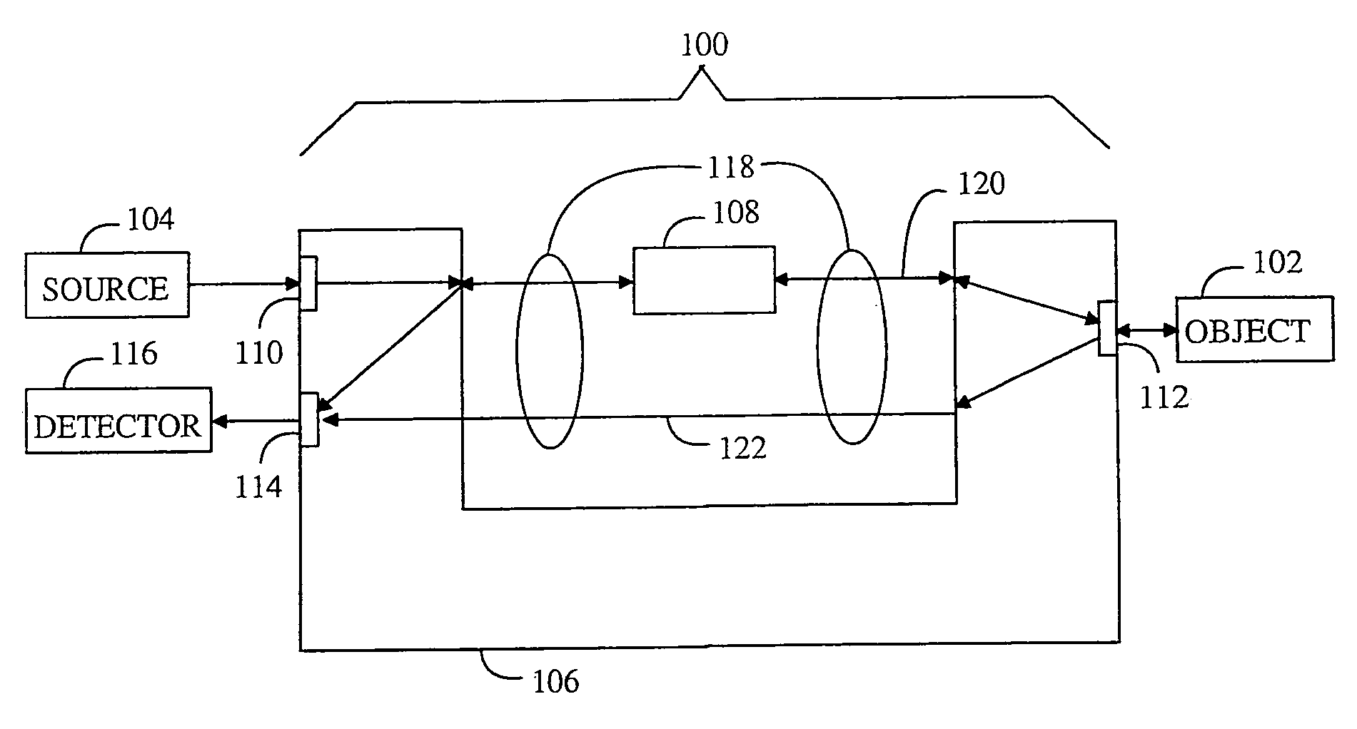
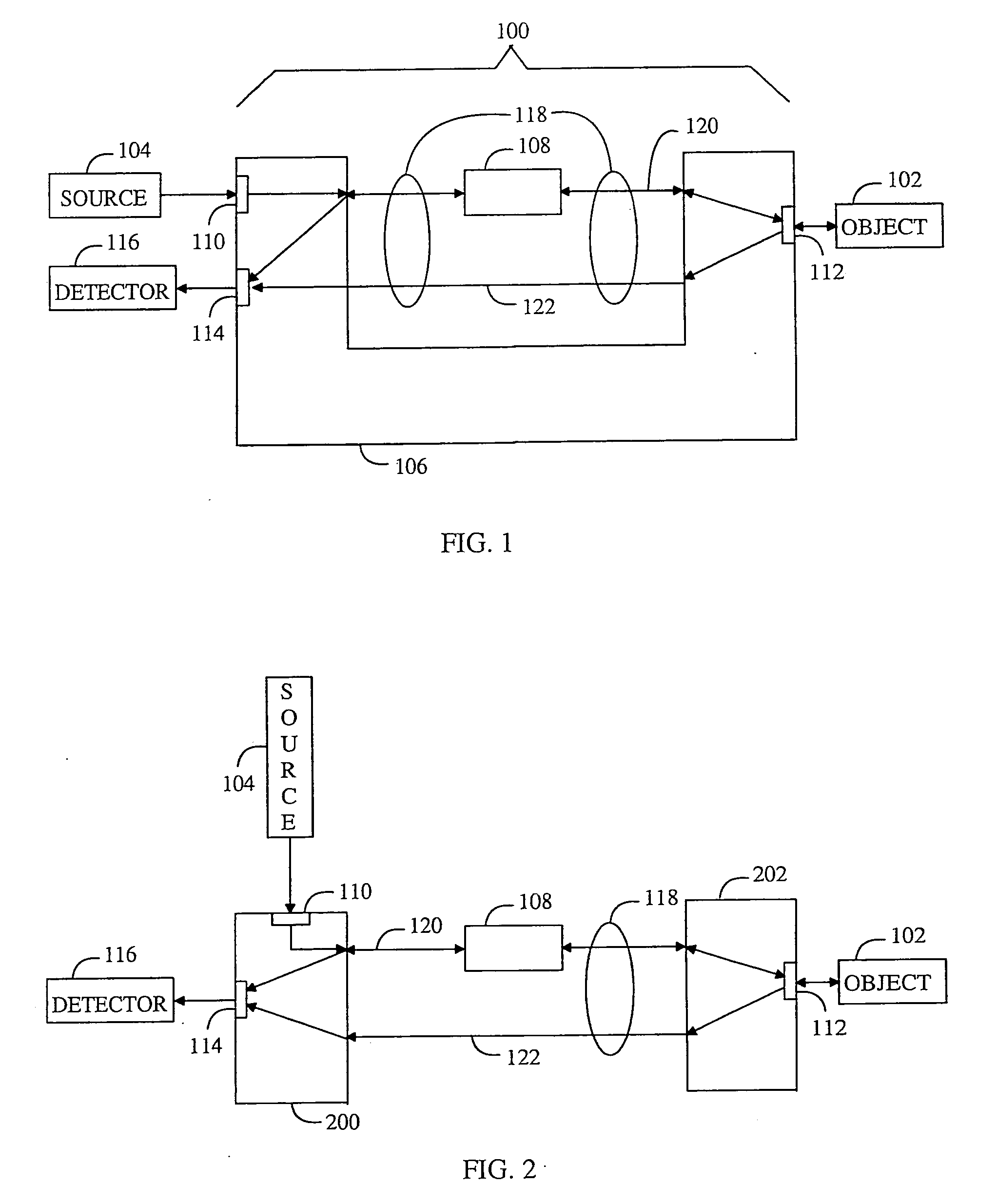
[0023] With reference to FIG. 1, an example of an optical element for a measuring apparatus is shown. The optical element 100 can be considered non-reciprocal which, means that the operation of the optical element 100 depends on the optical beam's propagation direction. The measuring apparatus may transmit the optical beam towards an object 102 in a transmission direction through the optical element 100 and the measuring apparatus may receive an optical beam reflected from the object 102 in a reception direction through the optical element 100. In the present application, the optical beam refers to electromagnetic radiation at wavelengths of including, but not limited to, about several hundred nanometers. The transmission direction denotes a direction from an optical source 104 to the object 102 and the reception direction denotes a direction from the object 102 to the optical source 104. The optical source 104 may be a monochromatic optical source such as a laser, a narrow band opt...
PUM
 Abstract
Description
Claims
Application Information