Alignment features for heat assisted magnetic recording transducers

a technology of magnetic recording transducer and alignment feature, which is applied in the field of data storage devices, can solve the problems of reducing the dynamic and shock performance of the suspension, requiring additional electrical connections, and heat the slider

Active Publication Date: 2006-10-19
SEAGATE TECH LLC
View PDF46 Cites 100 Cited by
  • Summary
  • Abstract
  • Description
  • Claims
  • Application Information

AI Technical Summary

Problems solved by technology

However, that approach requires additional electrical connections to the slider for the laser.
Also, the electrical power dissipated by the laser will substantially heat the slider, which is undesirable for obtaining the best performance from the reader.
The added mass of the laser on the slider (or suspension assembly) may also degrade the dynamic and shock performance of the suspension.
This approach eliminates the problems with the laser on the slider mentioned above, but introduces a new problem, which is how the optical connection is made between the fiber and the slider.
If the fiber is physically attached to the slider, the stiffness complicates the design of the gimbal structure that allows the slider to fly over the surface of the disc.
It has the disadvantage of the cost of a fiber pigtailed laser and because of its location it will be difficult to align the fiber lens during manufacturing.
These fiber types greatly increase the cost of the pigtailed laser diode and the alignment difficulty due to the rotational requirements.

Method used


Image

  • Alignment features for heat assisted magnetic recording transducers
  • Alignment features for heat assisted magnetic recording transducers
  • Alignment features for heat assisted magnetic recording transducers

Examples


Embodiment Construction

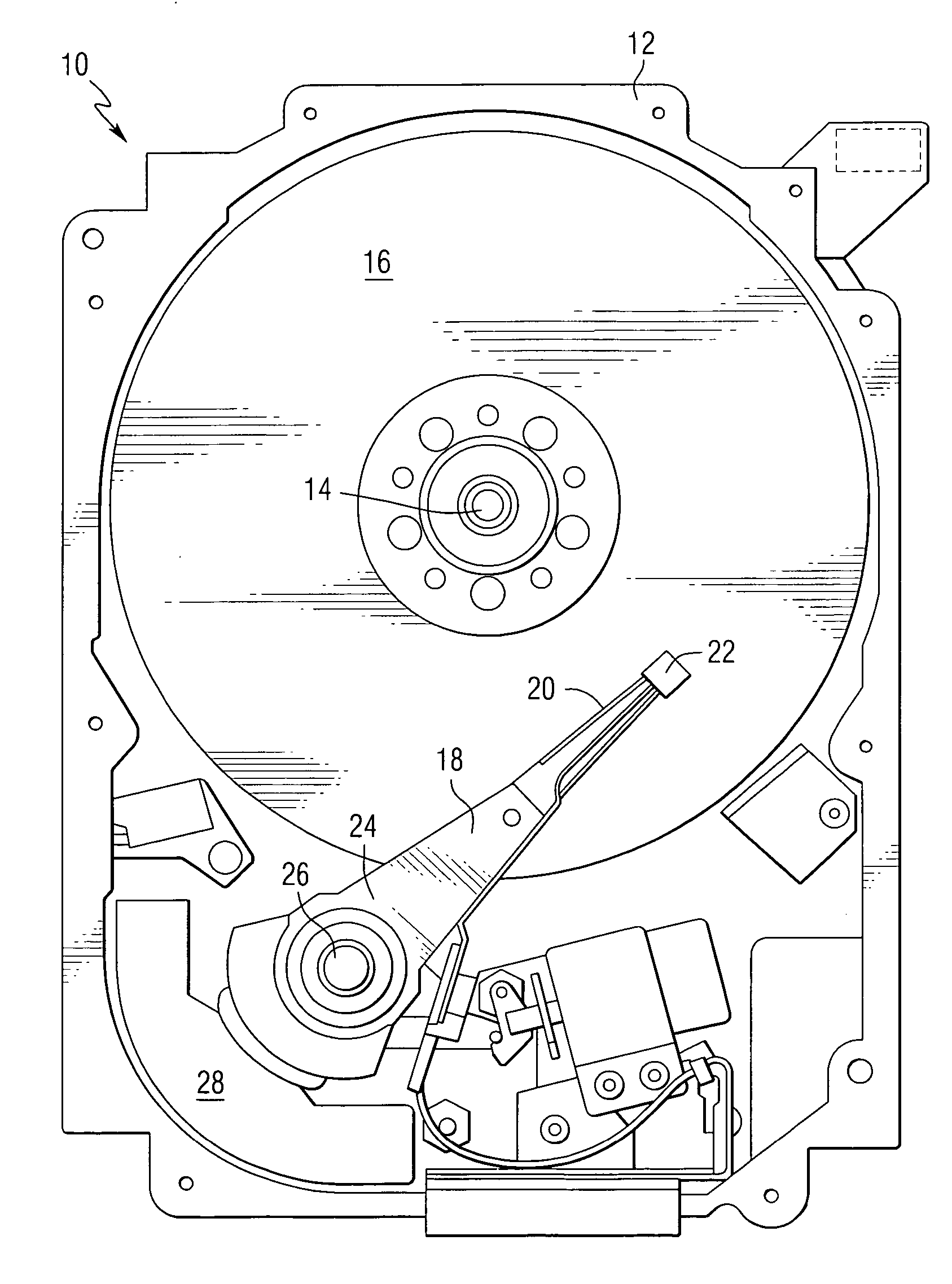
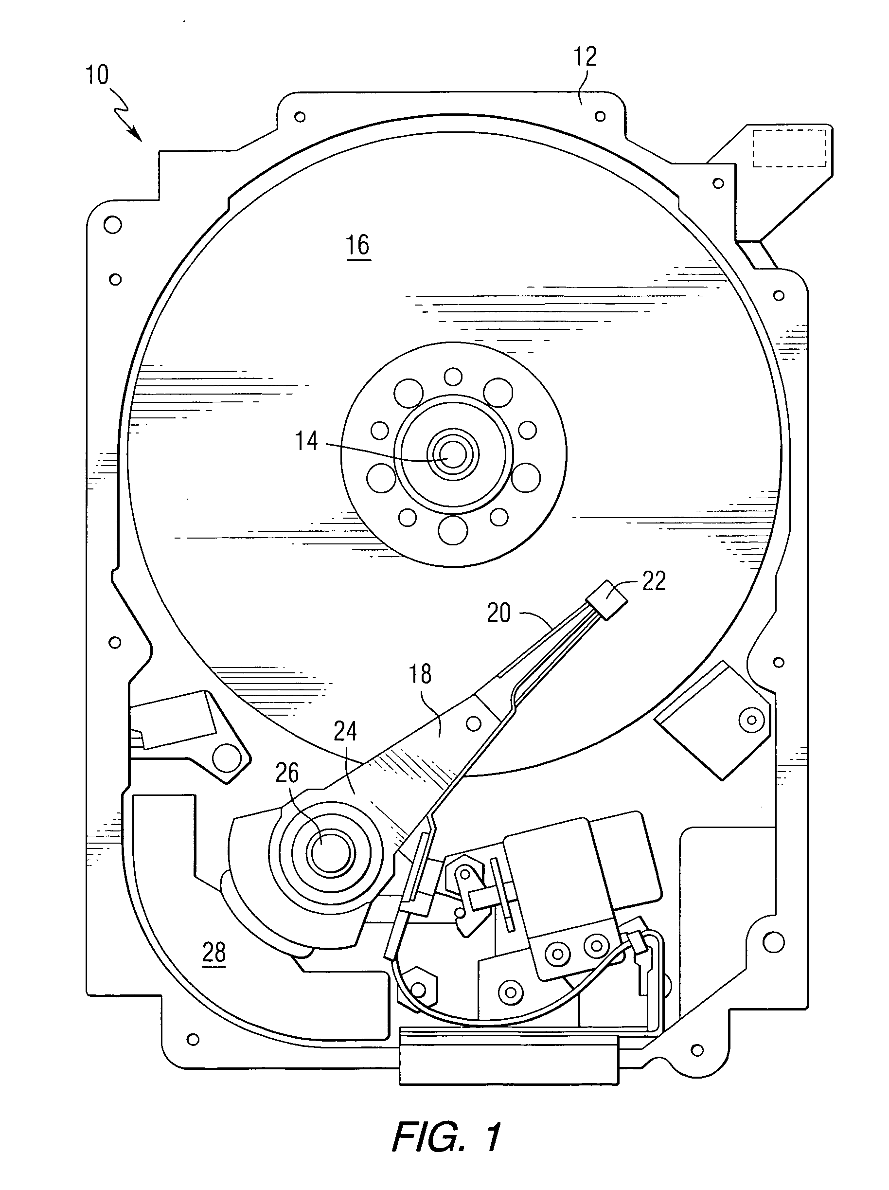
[0024]FIG. 1 is a pictorial representation of the mechanical portion of a disc drive 10 that can be constructed in accordance with the invention. The disc drive includes a housing 12 (with the upper portion removed and the lower portion visible in this view) sized and configured to contain the various components of the disc drive. The disc drive includes a spindle motor 14 for rotating at least one data storage medium 16 within the housing, in this case a magnetic disc. At least one arm 18 is contained within the housing 12, with each arm 18 having a first end 20 with a recording and / or reading head or slider 22, and a second end 24 pivotally mounted on a shaft by a bearing 26. An actuator motor 28 is located at the arm's second end 24, for pivoting the arm 18 on a pivot point on the axis of the shaft, to position the head 22 over a desired sector of the disc 16. The actuator motor 28 is regulated by a controller that is not shown in this view.

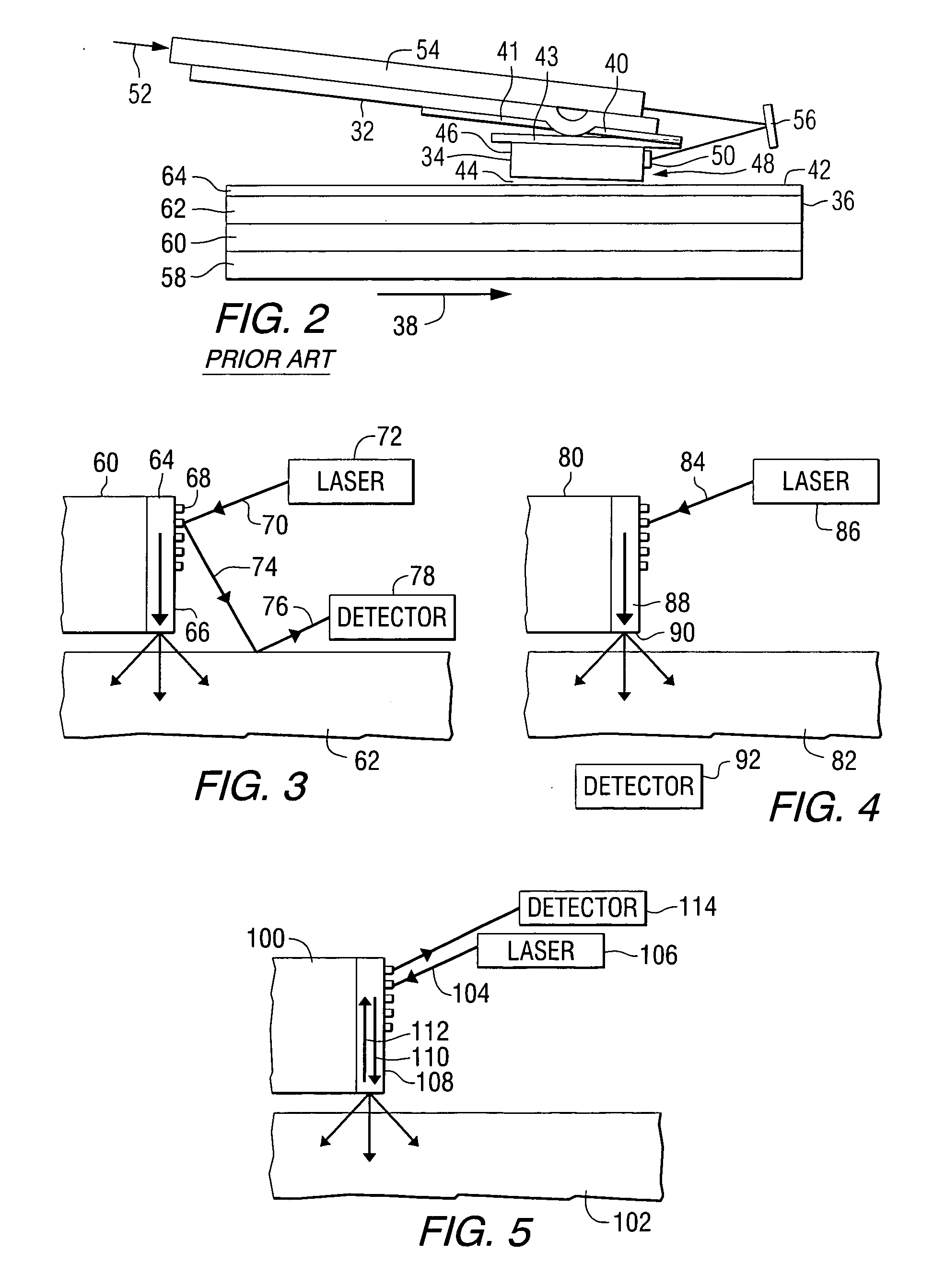
[0025]FIG. 2 is a schematic representa...


PUM

PropertyMeasurementUnit
free space distanceaaaaaaaaaa

Abstract

An apparatus comprises an optical transducer positioned adjacent to a storage medium and including a waveguide and a grating for coupling light into the waveguide, a light source transmitting light to the grating, and a detector for detecting a portion of the light, wherein the detected portion of the light has a magnitude that varies in response to the amount of light coupled into the waveguide.

Description

STATEMENT REGARDING FEDERALLY SPONSORED RESEARCH OR DEVELOPMENT [0001] This invention was made with United States Government support under Agreement No. 70NANB1H3056 awarded by the National Institute of Standards and Technology (NIST). The United States Government has certain rights in the invention.FIELD OF THE INVENTION [0002] This invention relates to data storage devices, and more particularly to such devices that can be used in optical recording and thermally assisted magnetic recording. BACKGROUND OF THE INVENTION [0003] In thermally assisted optical / magnetic data storage, information bits are recorded on a layer of a storage medium at elevated temperatures, and the heated area in the storage medium determines the data bit dimension. Heat assisted magnetic recording (HAMR) generally refers to the concept of locally heating a recording medium to reduce the coercivity of the recording medium so that the applied magnetic writing field can more easily direct the magnetization of t...

Claims


Application Information

Patent Timeline
Patent Type & Authority Applications(United States)
IPC IPC(8): G11B11/00
CPCG11B5/02G11B2005/0021G11B2005/0002
Inventor RAUSCH, TIMCHALLENER, WILLIAM ALBERTGAGE, EDWARD CHARLESMIHALCEA, CHRISTOPHE DANIELPENG, CHUBINGCHU, PATRICK BRECKOWGOMEZ, KEVIN ARTHUR
Owner SEAGATE TECH LLC
Why Eureka
Try Eureka