Glass test tube having protective outer shield

a test tube and glass technology, applied in the direction of laboratory glassware, instruments, analysis using chemical indicators, etc., can solve the problems of prone to accidental breakage and disfavored esr testing

Inactive Publication Date: 2006-10-19
CLINICAL DATA
View PDF36 Cites 38 Cited by
  • Summary
  • Abstract
  • Description
  • Claims
  • Application Information

AI Technical Summary

Benefits of technology

[0004] Accordingly, it is the principal feature of the present invention to provide an improved glass test t

Problems solved by technology

One problem with glass tubes is that they are prone to accidental breakage if dropped or otherwise mishandled by technicians.
Although plasti

Method used


Image

  • Glass test tube having protective outer shield
  • Glass test tube having protective outer shield
  • Glass test tube having protective outer shield

Examples


Embodiment Construction

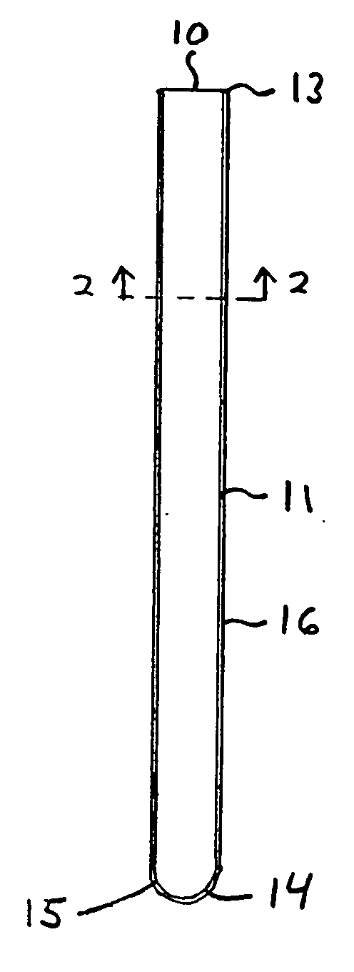
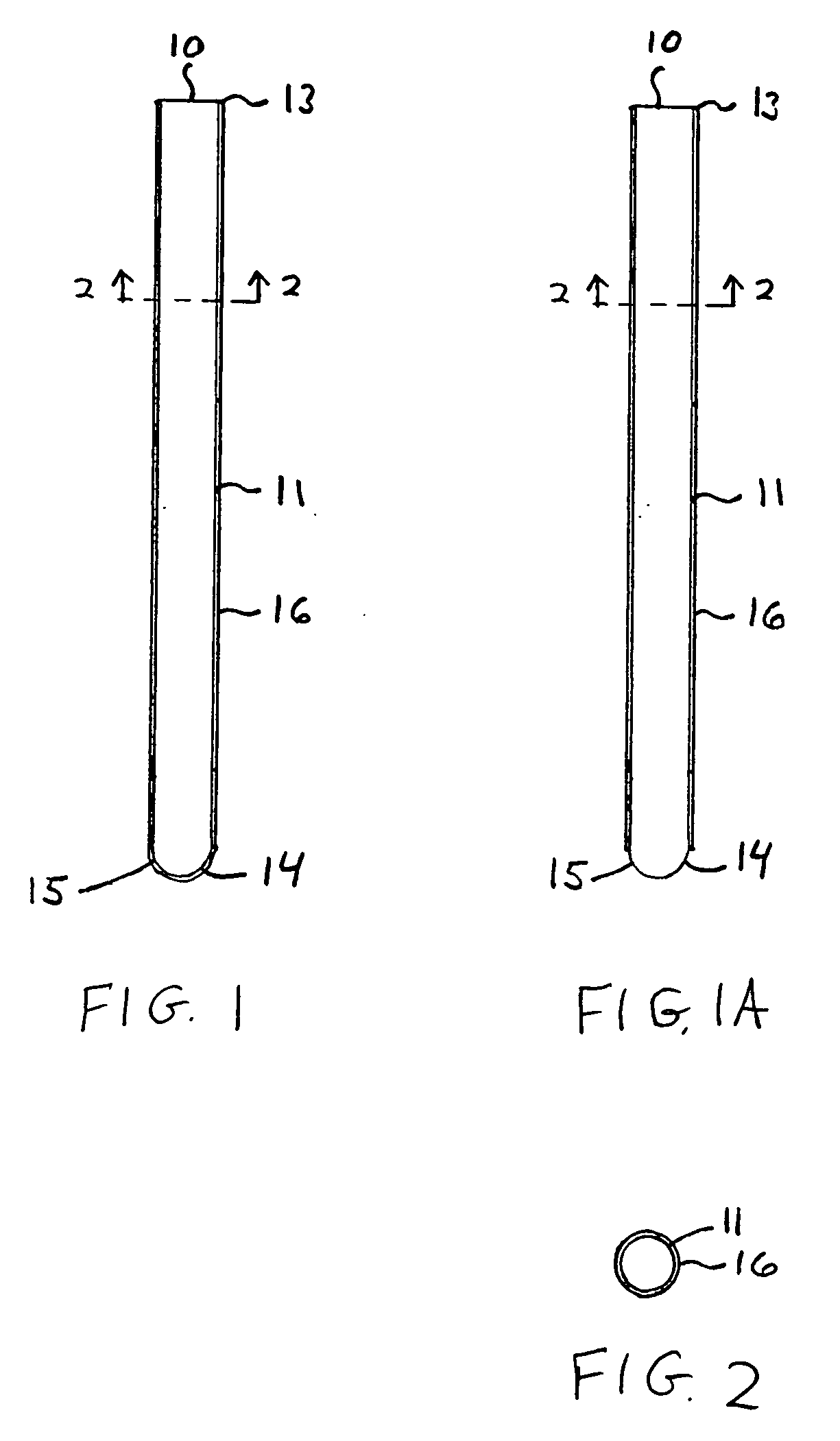
[0016] Referring to FIG. 1, a test tube 10 is shown having a hollow, cylindrical portion 11 with an open end 13 and a closed dome shaped end 14, and protective shield material 16 over the outer surface of cylinder portion 11 and the closed end 14. The cylindrical portion 11 with closed end 14 represents a typical glass test tube 15, such as used for containing blood or other bodily fluid specimen of a patient, upon which material 16 is applied.

[0017] Optionally, the protective material 16 may extend over cylinder portion 11 without covering closed end 14, as shown in FIG. 1A. This may be acceptable since the closed end 14 is often the thickest part of a glass test tube, and as such already provides a level of protection from breakage about end 14. A cross-section of the test tube 10 of FIGS. 1 and 1A is shown in FIG. 2.

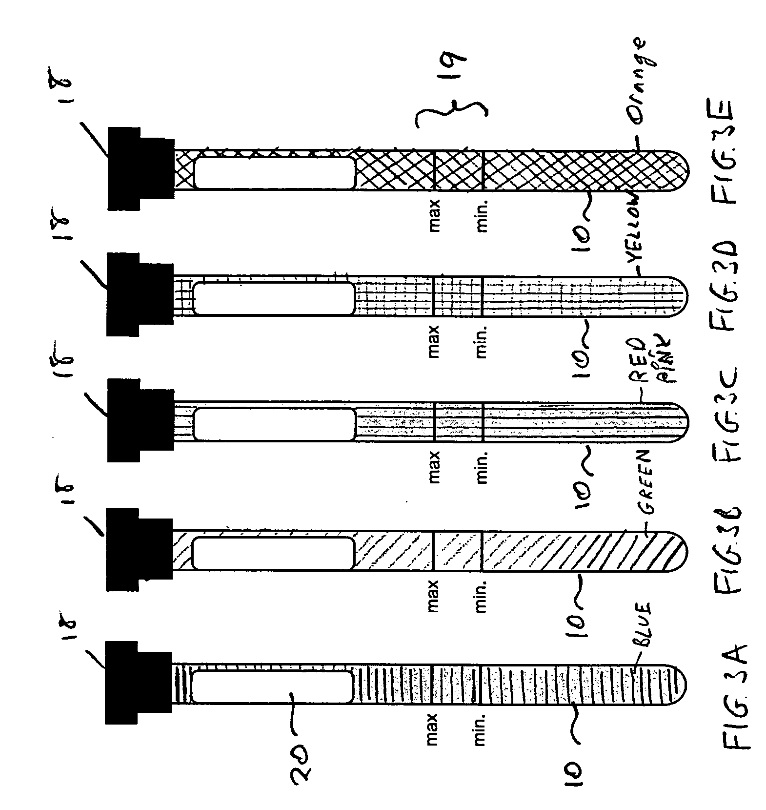
[0018] Test tube 10 is insertable into a slot of an automatic analyzer for optically measuring contents when contained in the test tube. For example, such automatic...


PUM


Abstract

An improved glass test tube is provided with a protective shield on the test tube's outer surface which protects the test tube from accidental breakage. The protective shield may be of a color which indicates that it has breakage protection. In one embodiment, the protective shield is provided by plastic material which is coated or sprayed on the outer surface of the glass test tube. In another embodiment, the protective shield is provided by one or more layers of wrapped sheet material, such as polyester film. The improved glass test tube is particularly useful in automatic analyzers that measure erythrocyte sedimentation rate.

Description

FIELD OF THE INVENTION [0001] The present invention relates to a glass test tube having a protective shield, and particularly, to a glass test tube having a protective shield of a material on the tube's outer surface which protects the test tube from accidental breakage. Such outer shield may be of a color indicating that the test tube has such breakage protection. The present invention is especially useful for glass test tubes which are traditionally use in automatic analyzers of medical specimens. BACKGROUND OF THE INVENTION [0002] Automatic analyzers and test equipment for measuring erythrocyte sedimentation rate (ESR) of blood are conventionally used in medical laboratories and physician offices. ESR represents the rate red blood cells fall in a period of time, and is often used by physicians in evaluating patient health. Blood is tested in such analyzers is a test tube sealed by a stopper with an anticoagulant. For more information on ESR Testing, see Methods for the Erythrocyt...

Claims


Application Information

Patent Timeline
IPC IPC(8): B01L9/00
CPCB01L3/5082B01L2300/0858B01L2200/085
Inventor STEIN, ISRAEL MAYER
Owner CLINICAL DATA
Why Eureka
Try Eureka