Bone plate

a bone plate and plate body technology, applied in the field of bone plates, can solve the problems of unusable devices and more expensive op techniques

Active Publication Date: 2006-10-19
DEPUY SYNTHES PROD INC
View PDF99 Cites 205 Cited by
  • Summary
  • Abstract
  • Description
  • Claims
  • Application Information

AI Technical Summary

Benefits of technology

[0009] A further advantage of the bone plate according to the invention is the possibility to use the at least three recesses in the hole in the plate to guide drilling bushings or guide bushings, by which the bone screws can be guided during their insertion. In this case the drilling bushings or guide bushings no longer need to be screwed into the holes in the plate (as is the case in the state-of-the-art), but due to the recesses need only to be inserted into the holes in the plate, resulting in a simple manner in the centre and direction of the axis of the hole. All that is required for this purpose is that the tips of the cannulated drilling bushings or guide bushings need to have the negative geometry of the holes in the plate, without any thread or other, similarly acting, structures. A snap-in mechanism may possibly be used in conjunction.
[0012] The internal jacket surface can have a concave, preferably spherical, tapered or ellipsoidal shape. This shape facilitates the insertion of a bone screw in such a manner that at the first contact of the bone screw with the internal jacket surface the bone screw is automatically pulled into the hole in the plate, without exerting prior a compression force on the bone via the bone plate, as is partly the case with devices known in the art.
[0016] The recesses may extend cylindrically or tapered from the upper side to the underside. The advantage of this is, that the recesses can be used for the fixing of a drilling bushing for pre-drilling or for the insertion of the Kirschner wires. Thus the drilling bushing no longer has to be screwed into the hole in the plate, only to be inserted without damaging the bearing area for the screw.

Problems solved by technology

A disadvantage of this construction is, on the one hand, the more expensive manufacture with an additional component (ring) and the danger that the tiny ring will fall out or be pushed out from the hole in the plate, thus making the device unusable, and, on the other hand, the more expensive OP technique because the axis of the ring has to be correspondingly aligned before inserting the screw.

Method used


Image

  • Bone plate
  • Bone plate
  • Bone plate

Examples


Embodiment Construction

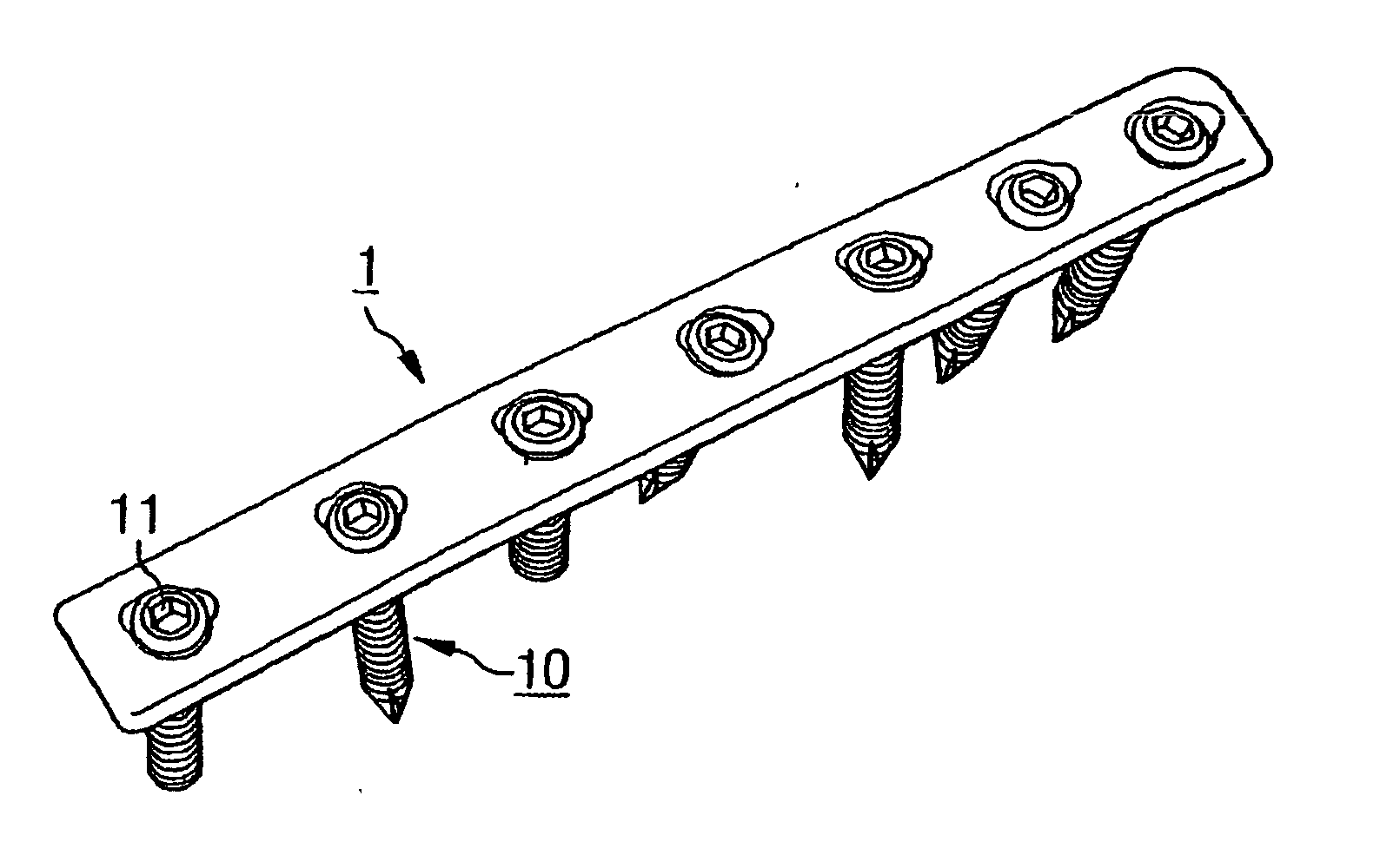
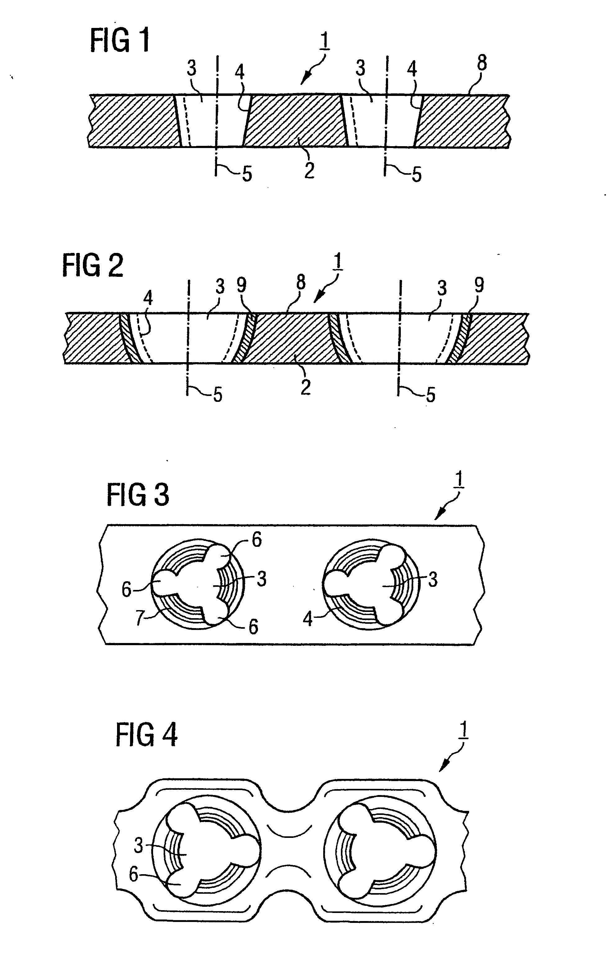
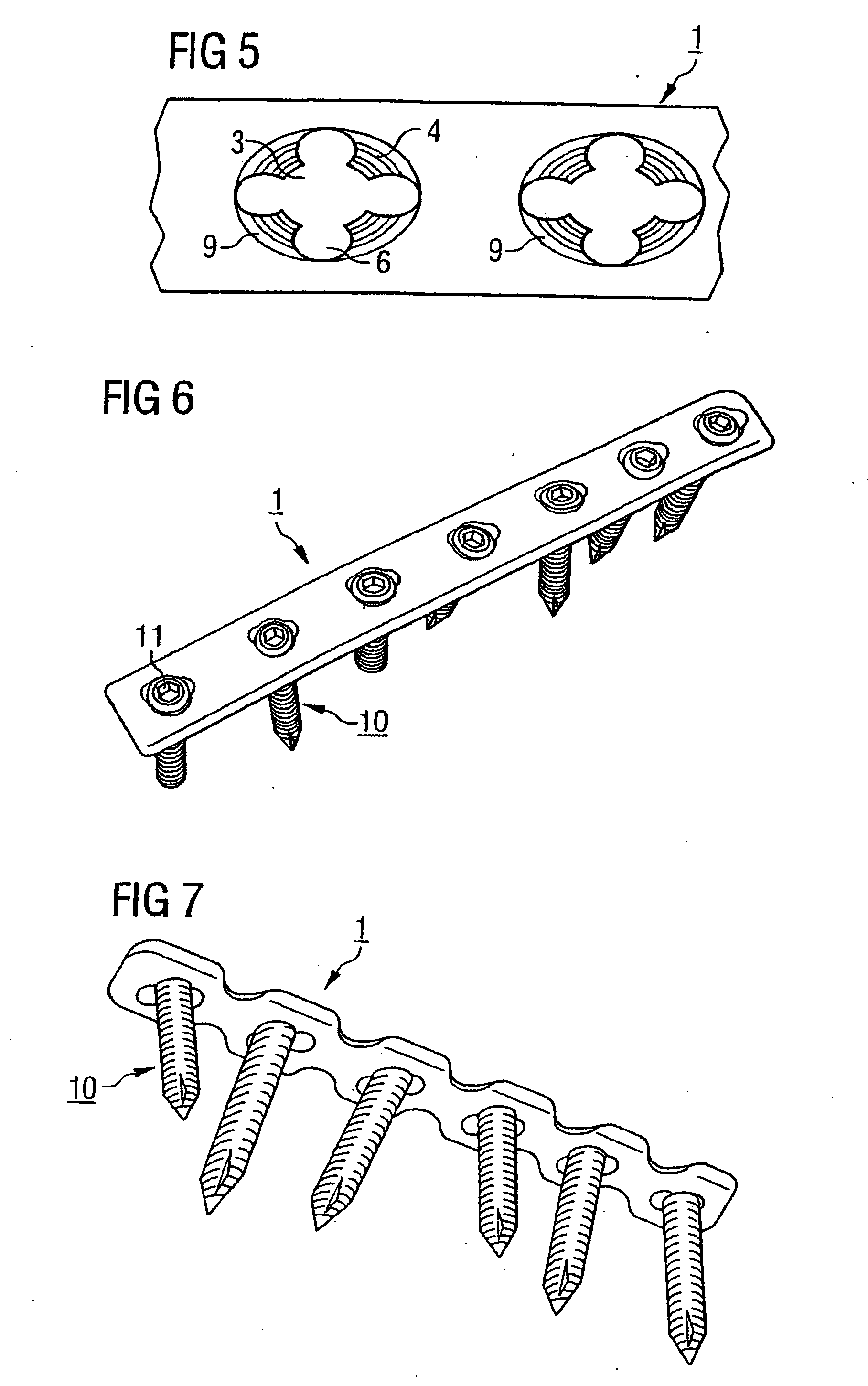
[0032] The bone plate 1 illustrated in FIGS. 1 and 3 has an underside 2 on the side of the bone, an upper side 8 and a plurality of holes 3 in the plate connecting the underside 2 with the upper side 8, the holes having a central hole axis 5. The holes 3 in the plate have an internal jacket surface 4 that tapers towards the underside 2. Furthermore, the internal jacket surface 4 has three recesses 6 which extend radially away from the hole axis 5 of the hole at a uniform distance of 120° from one another. Their peripheral extension is approximately 40° and they extend exclusively within the internal jacket surface 4. The recesses 6 extend tapered over the entire height of the bone plate 1 from the upper side 8 to the underside 2. In addition, the internal jacket surface 4 is provided with a three-dimensional structure 7 in the form of a thread.

[0033]FIG. 4 illustrates a variation of the execution according to FIG. 3, wherein the recesses extend radially away from the axis of the ho...


PUM

PropertyMeasurementUnit
elongation at breakaaaaaaaaaa

Abstract

A bone plate has an underside on the side of the bone, an upper side and a plurality of holes in the plate connecting the underside with the upper side, with a central hole axis. At least one of these holes in the plate has an internal jacket surface that tapers towards the underside, while the internal jacket surface has N≧3 recesses which extend radially away from the axis of the hole.

Description

RELATED APPLICATION DATA [0001] The present application is a continuation of the U.S. National Stage designation of co-pending International Patent Application No. PCT / CH2003 / 000577, filed Aug. 26, 2003, the entire content of which is expressly incorporated herein by reference thereto.FIELD OF THE INVENTION [0002] The invention relates to a bone plate for use in repairing bone fractures. BACKGROUND OF THE INVENTION [0003] Bone plates are known in the art and may be indicated for the entire skeleton. Particularly significant are, however, the usual large and small fragment indications for surgically treating bone breakages. [0004] From DE-A 198 32 513 a bone plate of the generic type is known. In the case of this known device, the angular alignment of the bone screws relative to the bone plate and their angularly stable fixing is achieved by a ring arranged between the head of the screw and the hole in the plate. A disadvantage of this construction is, on the one hand, the more expen...

Claims


Application Information

Patent Timeline
Patent Type & Authority Applications(United States)
IPC IPC(8): A61F2/30A61B17/80A61L27/18
CPCA61B17/8052A61B17/8057A61L27/18A61B17/8033A61L2430/02A61B17/80C08L77/12A61L31/06C08L71/00A61B17/68A61B17/58A61F2/28
Inventor SCHNEIDER, ROLF
Owner DEPUY SYNTHES PROD INC
Why Eureka
Try Eureka