Device and system for prosthetic knees and ankles

a technology for applied in the field of prosthetic knees and ankles, can solve the problems of storing less energy, releasing too late, and causing serious injury

Active Publication Date: 2006-10-19
MOTION CONTROL
View PDF9 Cites 112 Cited by
  • Summary
  • Abstract
  • Description
  • Claims
  • Application Information

AI Technical Summary

Problems solved by technology

If the foot is not dorsi-flexed during the swing phase, it would most likely catch on the walking surface and cause the person to stumble and fall, which may lead to serious injury.
If the dynamic response is too stiff, the foot bounces back too quickly.
If the spring is too soft, it stores less energy and releases too late.
Similar considerations apply in the case of such a prosthetic joint acting in the role of a knee, and the mechanical coupling of these two joints acting in combination complicates the creation of a solution which is satisfactory throughout the range of motion.
Prior prosthetic devices have difficulty efficiently accommodating a combination of slopes in sideward fashion that act upon the bottom of the foot during travel by an amputee.
The movements of the human foot are so complex, that even sophisticated prosthetic devices do not imitate many important aspects of the human ankle movement during walking.
In this respect, the available prosthetic ankle joints are not fully capable of movement from side to side, which is needed to encompass the required range of movements of the human ankle in inversion and eversion positions accompanied by the controlled return thereof to the medial or neutral position.
However, such devices do not capitalize on certain dynamic characteristics of the motion of the ankle joint in combination with the knee joint during the periods of plantar flexion and dorsi-flexion.
Other prior art joints do not adequately address the problems amputees face in getting lower limb prostheses to behave more like the original equipment.
This bi-polar mode shift regimen of control does not effectively serve a user's range of possible needs across different gait scenarios.
Moreover, the absence of a regulated impedance aspect as part of the control regimen for this design fails to address such persistent issues as the tendency of the lower limb to essentially kick the user's posterior at the culmination of swing phase, and the impact suffered at the terminal point of each swing phase in gait.
This means initiation is subject to a potential of premature or latent knee joint mode shift under certain exigencies of the terrain being navigated by a user.
The action of a human knee joint requires less mechanism complexity in replication than that of the ankle, because it is essentially a hinge, but coordinating its dynamic response characteristics to suitably match those of the ankle joint, over the range of intended cadence is challenging.
Furthermore, there are several other problems limiting the success of attempts in producing lower limb prosthetic devices.
Maintaining compactness of the ankle joint to match dimensions of variably sized shoes has traditionally been a design obstacle.
Similarly, issues surrounding the relationship between mechanical stress generated as a result of shear force and bending acting along the principal hinge axis exceeding material strength limits create engineering challenges.

Method used


Image

  • Device and system for prosthetic knees and ankles
  • Device and system for prosthetic knees and ankles
  • Device and system for prosthetic knees and ankles

Examples


Embodiment Construction

[0025] Reference will now be made to the exemplary embodiments illustrated in the drawings, and specific language will be used herein to describe the same. It will nevertheless be understood that no limitation of the scope of the invention is thereby intended. Alterations and further modifications of the inventive features illustrated herein, and additional applications of the principles of the inventions as illustrated herein, which would occur to one skilled in the relevant art and having possession of this disclosure, are to be considered within the scope of the invention.

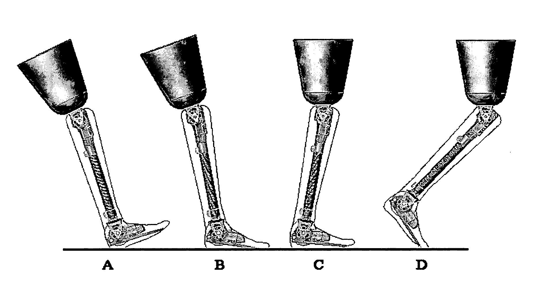
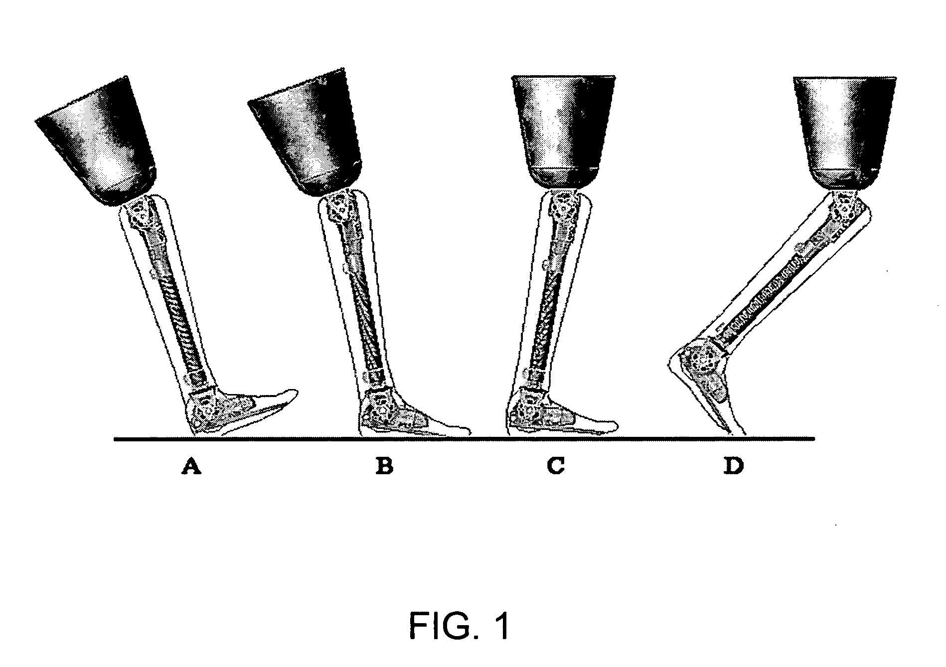
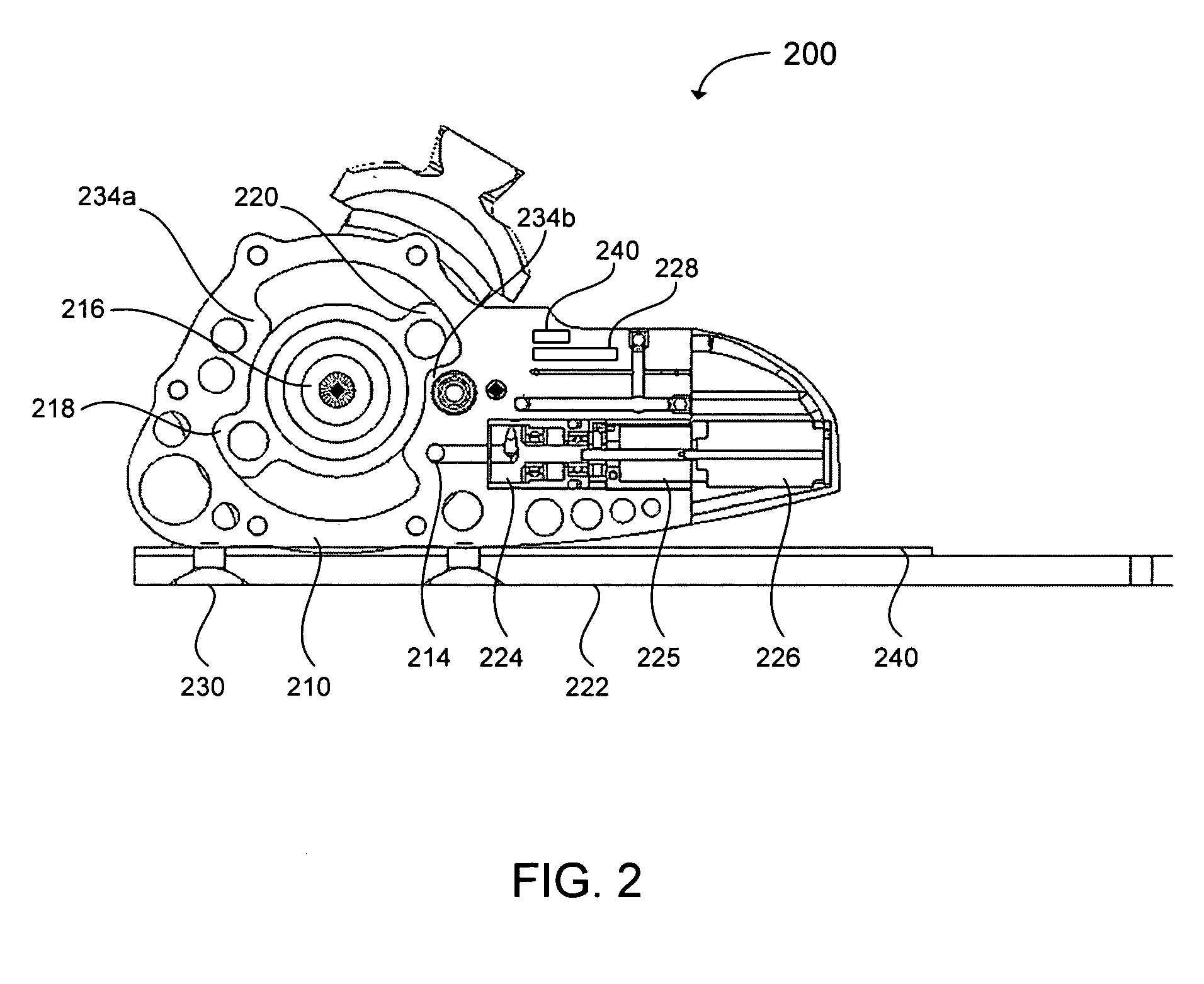
[0026] The present invention includes an energy storing prosthetic device that may have controlled impedance in an electro-hydraulic multi-axis prosthetic knee or ankle. This controlled-impedance transfemoral prosthesis device can include a hydraulic ankle, coupled to an energy storing foot via an elastomeric interface. A limb-like link can be included that is a hydraulic knee mounted by prosthetic socket to th...


PUM


Abstract

A device and system is provided for a prosthetic device having an articulating joint for a leg amputee. The device includes a joint housing forming a chamber, and the chamber has a first opening. A rotary hub can be disposed within the joint housing and configured to act as the articulating joint. One or more vanes can extend outwardly from the rotary hub, and the vane is configured to actuate fluid flow through the first opening.

Description

[0001] Priority of U.S. Provisional patent application Ser. No. 60 / 666,388 filed on Mar. 29, 2005 is claimed.FIELD OF THE INVENTION [0002] The present invention relates generally to prosthetic devices. BACKGROUND [0003] An intact human foot, connected to its ankle, travels through stance and swing phases of a gait cycle during each stride of motion, whether the motion involves walking, jogging, or running. By adjusting the stiffness and damping characteristics of a prosthetic ankle or knee mechanism, the springiness of the intact natural human foot and its corresponding natural human joints may be mimicked, thereby optimizing the prosthetic for the desired motion of the wearer. The characteristics that are desired to store and release energy appropriately for walking tend to oppose those best suited to fast walking and running. [0004] In a stance phase, the foot is in contact with the ground and the weight of a person is supported on the foot. In a swing phase, the foot is off the g...

Claims


Application Information

Patent Timeline
Patent Type & Authority Applications(United States)
IPC IPC(8): A61F2/66A61F2/74A61F2/64
CPCA61F2/64A61F2/6607A61F2/68A61F2/72A61F2002/5003A61F2002/5006A61F2002/7625A61F2002/6854A61F2002/704A61F2002/741A61F2002/744A61F2002/745A61F2002/748A61F2002/5033A61F2/70A61F2/741A61F2/744A61F2/74A61F2/748
Inventor IVERSEN, EDWIN KAYSEARS, HAROLD H.DYCK, ARTHUR D.KUNZ, STEVEN R.JACOBS, JOSEPH ANTHONYLINDER, JAMES R.STRAZDINS, PETER K.
Owner MOTION CONTROL
Why Eureka
Try Eureka