Spark plug and method for manufacturing the spark plug

a technology of spark plugs and spark plugs, which is applied in the manufacture of spark plugs, spark plugs, electrical equipment, etc., can solve the problems of excessive softening of /b>, increasing the difficulty of welding, so as to achieve easy welding. the effect of good joint condition and further facilitation of the joining process

Inactive Publication Date: 2006-10-26
NGK SPARK PLUG CO LTD
View PDF20 Cites 25 Cited by
  • Summary
  • Abstract
  • Description
  • Claims
  • Application Information

AI Technical Summary

Benefits of technology

[0010] An object of the present invention is to provide a spark plug in which a noble metal spark portion is protrusively formed on a ground electrode and which is configured such that, even when used in an environment where a spark is apt to drift under a gas flow, the ground electrode is unlikely to suffer uneven ablation, as well as a method for manufacturing the spark plug.

Problems solved by technology

However, recently, in order to enhance fuel economy and to cope with stricter exhaust gas regulations, the trend is toward lean air-fuel mixture (lean burn), and thus ignition conditions are growing increasingly severe.
Therefore, when resistance heating to a temperature required for alloying with Ir is performed, as shown in FIG. 13 of the accompanying drawings, the main metal portion of a ground electrode 4 is excessively softened and significantly deformed as compared with a noble metal chip 32′; hence, formation of a normal spark portion becomes very difficult.

Method used


Image

  • Spark plug and method for manufacturing the spark plug
  • Spark plug and method for manufacturing the spark plug
  • Spark plug and method for manufacturing the spark plug

Examples


examples

[0112] The invention is now explained in greater detail by reference to the following Examples which should not be construed as limiting the invention.

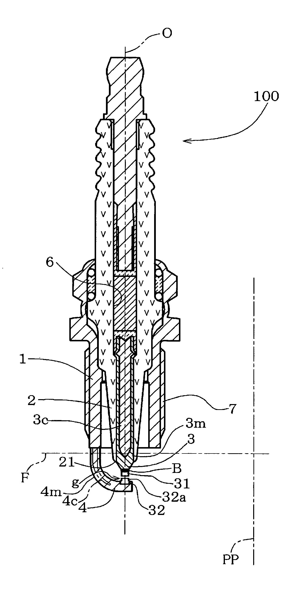
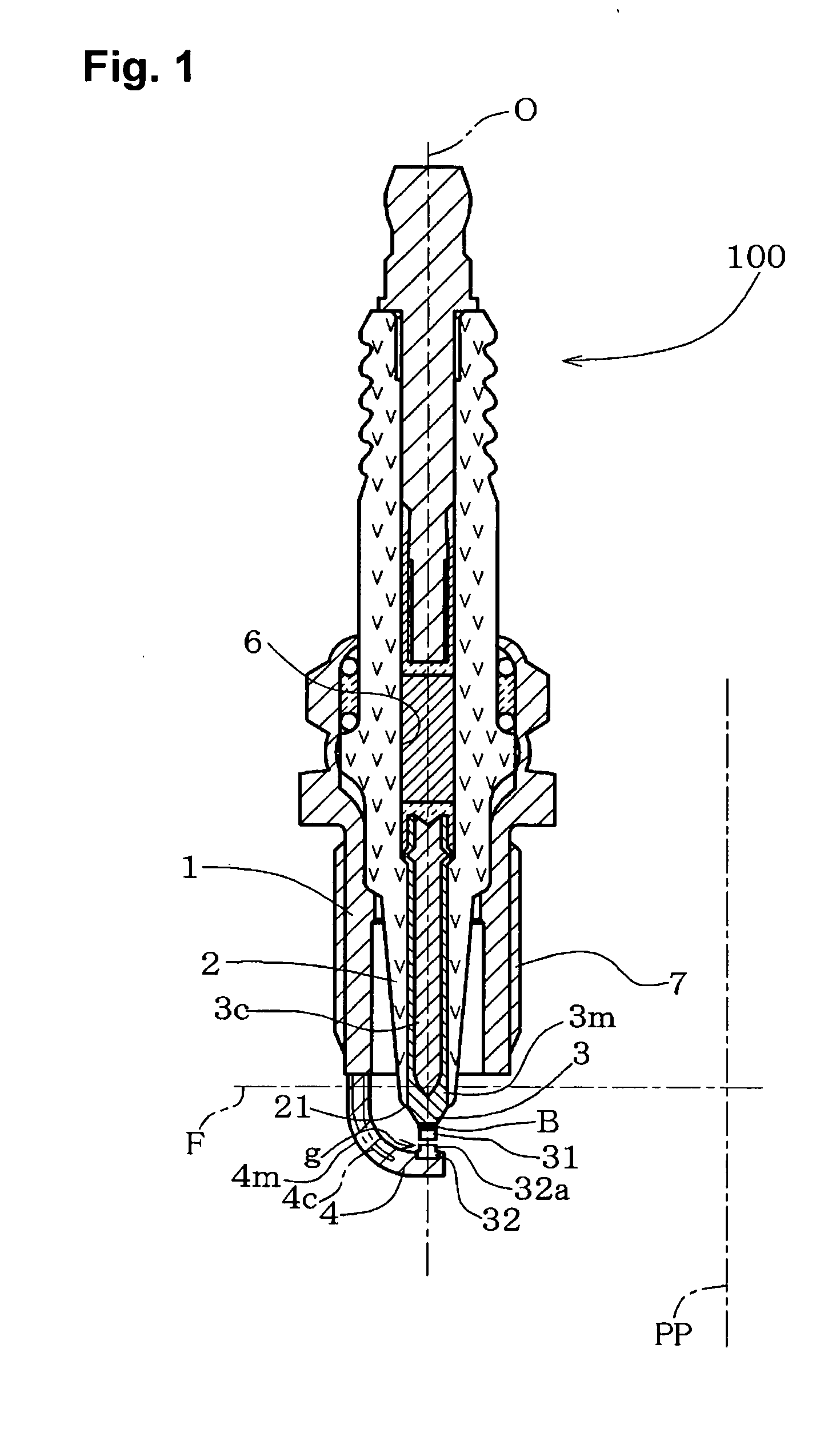
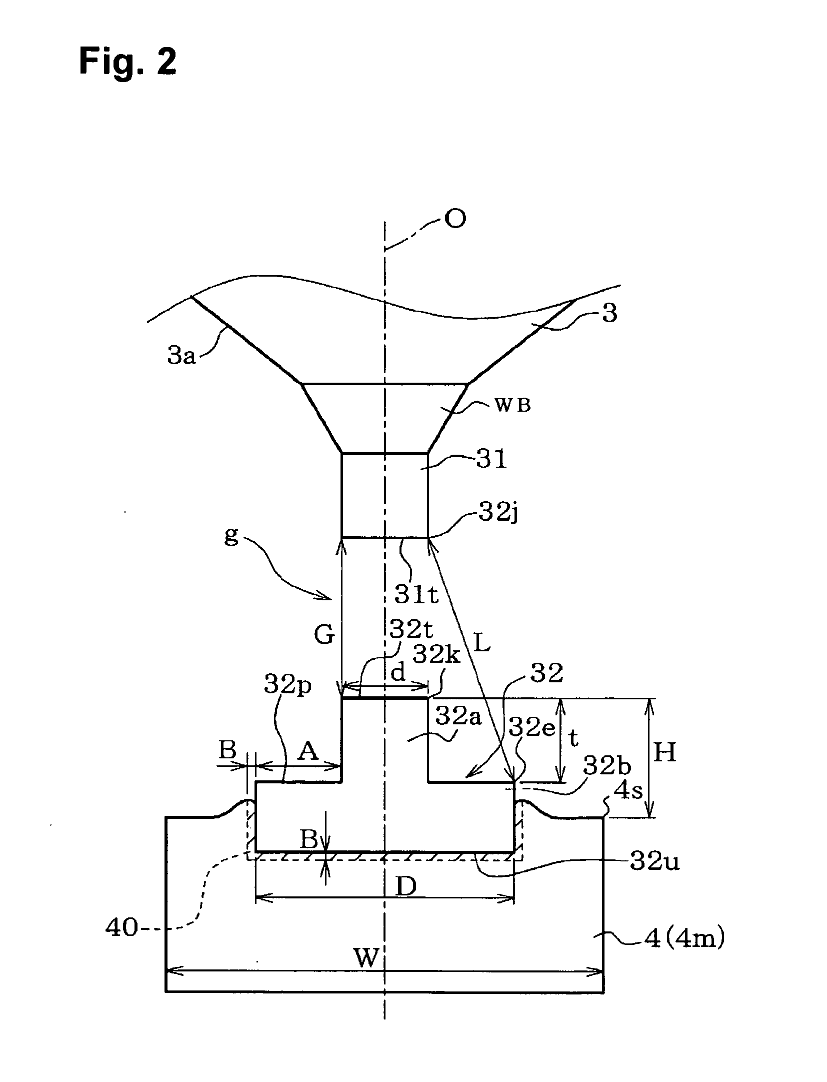
[0113] Various test samples of the spark plug 100 shown in FIGS. 1 and 2 were prepared in the following manner. The ground-electrode spark portion 32 shaped as shown in FIG. 2 was manufactured from a Pt-20% by mass Ir alloy by header working as shown in Steps 1 and 2 of FIG. 3 such that the body portion 32b had a thickness of 0.3 mm and a diameter D of 1.5 mm; the protrusive portion 32a had a height t of 0.1-2.0 mm; the distal end surface 32t had a diameter d of 0.3-1.5 mm; and the top surface (peripheral exposed-region surface 32p) had a width A of 0-0.7 mm. The resultant piece was resistance-welded to the ground electrode 4 formed from INCONEL 600, according to Steps 3 and 4 of FIG. 3. Resistance welding conditions were set such that the applied current was 900 A, and the applied load was 150 N. The welded ground-electrode spark po...


PUM

PropertyMeasurementUnit
diameteraaaaaaaaaa
heightaaaaaaaaaa
melting pointaaaaaaaaaa

Abstract

A ground-electrode spark portion 32 is formed from a noble metal which contains Pt as a main component, and is joined to a main metal portion of the ground electrode 4 via an alloy layer which has a thickness ranging from 0.5 μm to 100 μm and in which the noble metal that constitutes the ground-electrode spark portion 32 and the metal that constitutes the main metal portion of the ground electrode 4 are alloyed with each other. The ground-electrode spark portion 32 is configured such that a distal end surface 32t facing a spark discharge gap g is smaller in diameter than a bottom surface 32u joined to the ground electrode 4; and the distal end surface 32t is protrusively located beyond the side surface 4s of the ground electrode 4. When the ground-electrode spark portion 32 is viewed in plane from the distal end surface 32t, a portion of the surface of the ground-electrode spark portion 32 is viewed as a peripheral exposed-region surface 32p which is exposed on the side surface 4s of the ground electrode 4 so as to surround the distal end surface 32t.

Description

CROSS-REFERENCE TO RELATED APPLICATION [0001] This application is a Continuation of U.S. application Ser. No. 10 / 465,552 filed Jun. 20, 2003; the above-noted application incorporated herein by reference in its entirety.BACKGROUND OF THE INVENTION [0002] 1. Field of the Invention [0003] The present invention relates to a spark plug, as well as to a method for manufacturing the same. [0004] 2. Description of the Related Art [0005] In recent years, in response to increasing demand for high performance of an internal combustion engine such as an automobile gasoline engine, a spark plug used for providing ignition has been required to enhance ignition performance and to reduce discharge voltage. A reduction in the diameter of a spark portion of a center electrode is effective for enhancing ignition performance and reducing discharge voltage. Thus, many spark plugs have employed a structure in which a noble metal chip is joined to a diameter-reduced distal end of a center electrode so as ...

Claims


Application Information

Patent Timeline
Patent Type & Authority Applications(United States)
IPC IPC(8): H01T13/20H01T13/32H01T13/00H01T21/02
CPCH01T21/02H01T13/32H01T13/00
Inventor TERAMURA, HIDEKIKATO, TOMOAKITORII, KAZUYOSHI
Owner NGK SPARK PLUG CO LTD
Why Eureka
Try Eureka