MEMS actuators and switches

a technology of actuators and switches, applied in the field of microelectromechanical systems, can solve the problems of increasing the overall cost of a system using mems switches, damage to unprotected mems switches, etc., and achieve the effect of reducing the overall system manufacturing cost and increasing current carrying capacity

Inactive Publication Date: 2006-10-26
RESEAUX MEMS SOC & COMMANDITE
View PDF11 Cites 32 Cited by
  • Summary
  • Abstract
  • Description
  • Claims
  • Application Information

AI Technical Summary

Benefits of technology

[0012] We have developed improved MEMS structures employing movable conductive member and a number of current-carrying stationary contact terminals which advantageously permits higher current carrying capability that prior art devices in which currents flowed through movable conductive members. Advantageously, and in sharp contrast to the prior art , our inventive structures may carry currents in excess of 1.0 amp without the need for additional current limiting devices. Consequently, systems employing our inventive structures exhibit significantly lower overall system manufacturing costs.

Problems solved by technology

For instance, one factor which generally increases the overall costs of a system using MEMS switches is the inclusion of any additional protection that is oftentimes required in particular markets.
Such current peaks—while usually brief in length—can damage unprotected MEMS switches.

Method used


Image

  • MEMS actuators and switches
  • MEMS actuators and switches
  • MEMS actuators and switches

Examples


Embodiment Construction

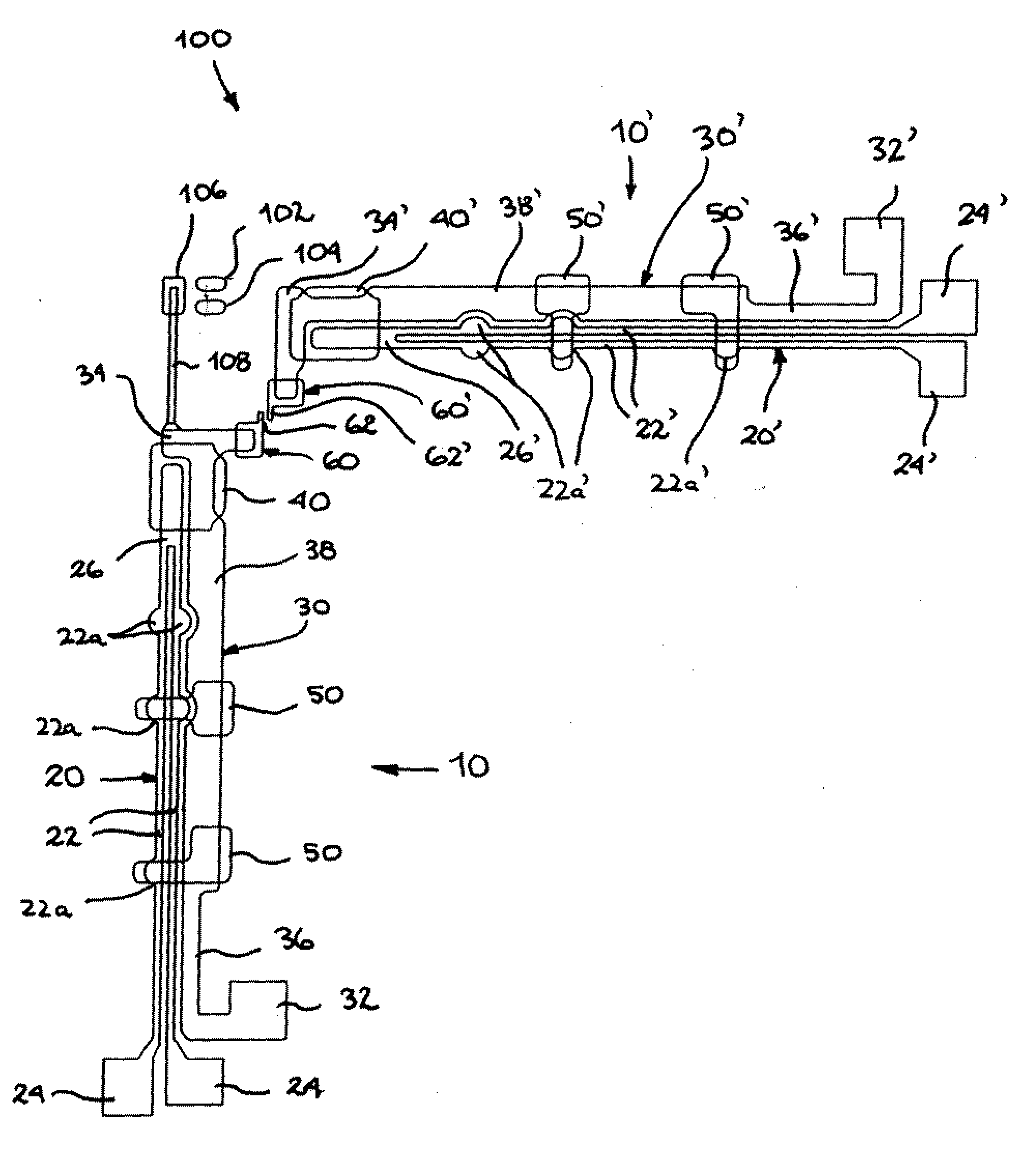
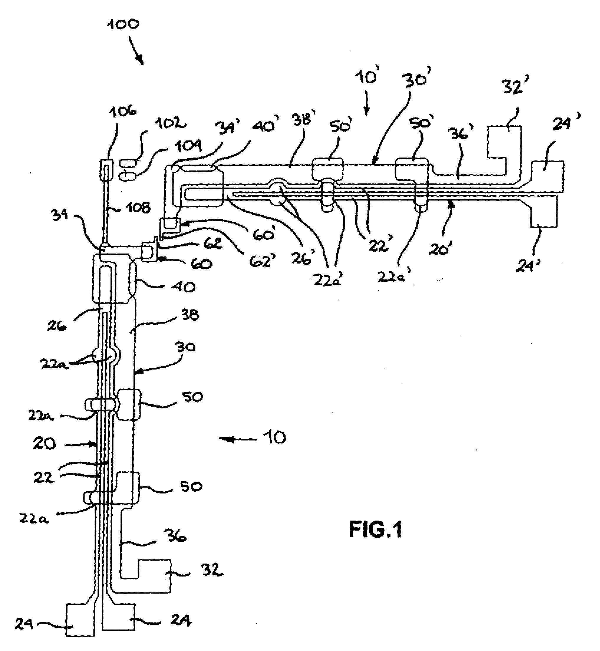
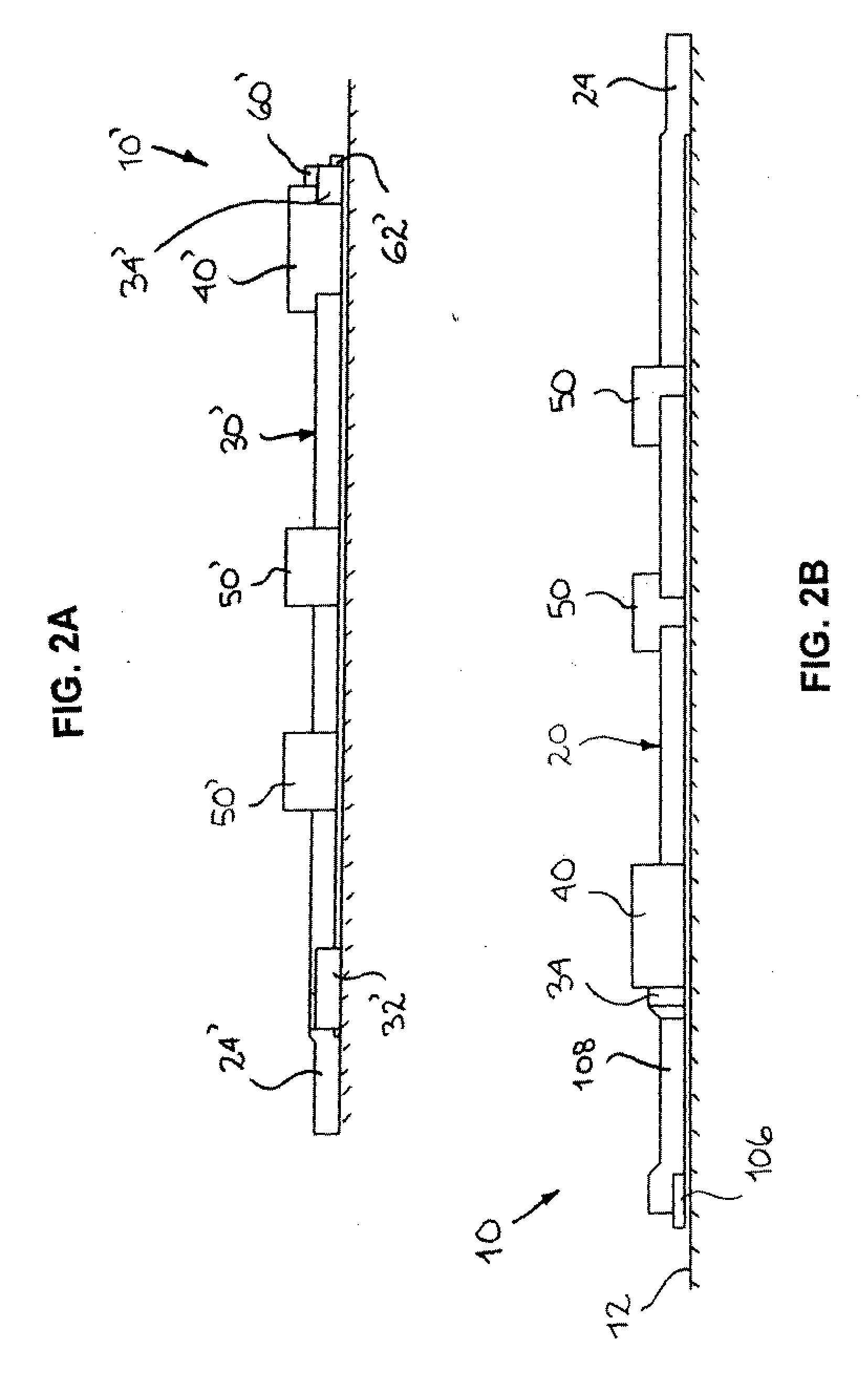
[0032]FIG. 1 shows an example of a MEMS switch (100) constructed according to the principles of the present invention. The switch (100) comprises two MEMS actuators (10, 10′). The MEMS switch (100) is used to selectively close or open a circuit between a pair of contact terminals (102, 104) using a movable conductive member (106) mounted at the end of a support arm (108).

[0033] When the MEMS switch (100) is in a closed position, the contact terminals (102, 104) are in electrical engagement—that is to say an electrical current may flow between the two contact terminals (102,104). This electrical engagement is realized when the movable conductive member (106) electrically “shorts” the pair of contact terminals (102,104).

[0034] Conversely, when the MEMS switch (100) is in an open position, the contact terminals (102, 104) are not electrically engaged and no appreciable electrical current flows between them. In preferred embodiments, the movable conductive member (106) is gold plated....


PUM


Abstract

MEMS structures employing movable conductive member and a number of current-carrying stationary contact terminals which advantageously permit higher current carrying capability that prior art devices in which currents flowed through movable conductive members. Current carrying capability in excess of 1.0 amp without the need for additional current limiting devices is realized thereby lowering overall system manufacturing costs for systems employing our structures.

Description

CROSS REFERENCE TO RELATED APPLICATIONS [0001] This application claims the benefit of U.S. Provisional Application No. 60 / 662,829 filed Mar. 18, 2005, which describes an improvement over U.S. patent application Ser. No. 10 / 782,708 filed Feb. 17, 2004 claiming the benefit of U.S. Provisional Application No. 60 / 464,423 filed Apr. 22, 2003, the entire file wrapper contents of which applications are herein incorporated by reference as though set forth at length.FIELD OF THE INVENTION [0002] This application relates generally to the field of microelectromechanical systems (MEMS) and in particular to improved MEMS devices that do not require additional current limiting devices. BACKGROUND OF THE INVENTION [0003] Microelectromechanical systems (MEMS) are small, movable, mechanical structures built using well-characterized, semi-conductor processes. Advantageously, MEMS can be provided as actuators, which have proven to be very useful in many applications. [0004] Present-day MEMS actuators ...

Claims


Application Information

Patent Timeline
Patent Type & Authority Applications(United States)
IPC IPC(8): H01H51/22
CPCH01H61/04H01H2001/0047H01H2061/008H01H2061/006H01H2001/0068B81B7/00B81B7/02
Inventor LU, JUNMENARD, STEPHANE
Owner RESEAUX MEMS SOC & COMMANDITE
Why Eureka
Try Eureka