Liquid crystal display device suitable for display of moving pictures

a liquid crystal display and moving picture technology, applied in static indicating devices, non-linear optics, instruments, etc., can solve the problems of increasing the complexity of the control circuit construction, increasing the speed at which image data is read out from the frame memory, and difficult to display images with a high brightness, etc., to achieve the effect of increasing the readout increasing the transfer rate of image data, and prolonging the lighting period of the back lighting

Inactive Publication Date: 2006-10-26
SHARP KK
View PDF4 Cites 27 Cited by
  • Summary
  • Abstract
  • Description
  • Claims
  • Application Information

AI Technical Summary

Benefits of technology

[0018] The abovementioned aspects of the present invention make it possible to drive the liquid crystal layer by an overdrive system without increasing the readout rate of image data from the frame memory or increasing the transfer rate of image data to the data driver, and also make it possible to lengthen the lighting period of the back lighting. Accordingly, an image display with a high image quality can be obtained while suppressing the blurring of moving pictures.

Problems solved by technology

As a result of this, it is necessary to increase the transfer rate of image data to the data driver, and the problem of increase complexity of the control circuit construction arises.
In cases where the driving time of the liquid crystal layer cannot be shortened, the stable period following the variation in the transmissivity of the liquid crystal layer within one frame is shortened, and the back-light lighting period becomes shorter, thus making it difficult to display images with a high brightness.
Furthermore, in cases where the image data is temporarily stored in a frame memory, the speed at which this image data is read out from the frame memory must also be increased, and in this regard as well, the control circuit construction tends to become more complicated.

Method used


Image

  • Liquid crystal display device suitable for display of moving pictures
  • Liquid crystal display device suitable for display of moving pictures
  • Liquid crystal display device suitable for display of moving pictures

Examples


Embodiment Construction

[0032] Embodiments of the present invention will be described below with reference to the attached figures. However, the technical scope of the present invention is not limited to these embodiments; this scope extends to the matters described in the Claims, and equivalent matters thereof.

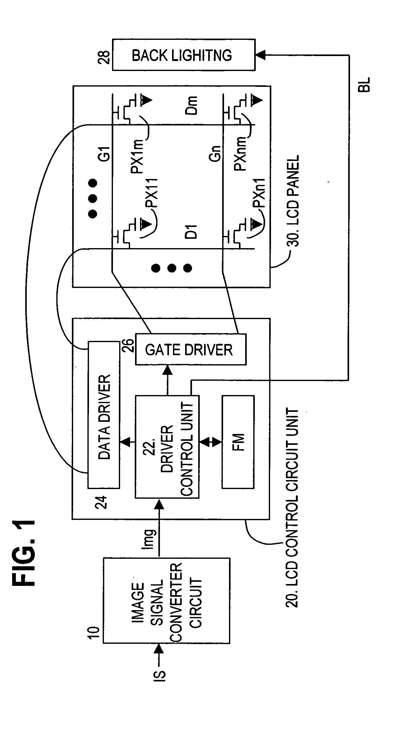
[0033]FIG. 1 is a schematic structural diagram of the liquid crystal display device. The liquid crystal display device is constructed from an image signal converter circuit 10, a liquid crystal control circuit unit 20, and a liquid crystal display panel 30. The image signal converter circuit 10 converts an image source signal IS from a personal computer, television tuner or the like into an image signal Img for each pixel corresponding to the liquid crystal display panel, e.g., in terms of panel size, pixel density and the like. The liquid crystal control circuit unit 20 temporarily stores the image data signals Img that are supplied in a frame memory FM. A driver control unit 22 reads out the imag...


PUM


Abstract

A back lighting has first and second back lighting units which respectively supply light to a first display region that has first gate lines of the liquid crystal display panel, and a second display region that has second gate lines, the liquid crystal control circuit unit performs, during the frame period, starting driving that drives the pixels at a first voltage corresponding to the image data, and hold driving that drives the pixels at a second voltage corresponding to the image data, successively for the first display region, and then performs the starting driving and hold driving successively for the second display region, and the first back lighting unit is lit after the starting driving of the first display region, while the second back lighting unit is lit after the starting driving in the second display region.

Description

CROSS-REFERENCE TO RELATED APPLICATIONS [0001] This application is based upon and claims the benefit of priority from the prior Japanese Patent Application No. 2005-056486, filed on Mar. 1, 2005, the entire contents of which are incorporated herein by reference. BACKGROUND OF THE INVENTION [0002] 1 . Field of the Invention [0003] The present invention relates to a liquid crystal display device which is suitable for the display of moving pictures, and more particularly relates to a liquid crystal display device in which the liquid crystal response speed is increased, and blurring of the moving pictures is suppressed. [0004] 2. Description of the Related Art [0005] Liquid crystal display devices are widely used as space-saving flat type displays, and in recent years have begun to be used as television display devices. In liquid crystal display devices, a voltage corresponding to a brightness value is applied across electrodes between which a liquid crystal layer is sandwiched, and des...

Claims


Application Information

Patent Timeline
Patent Type & Authority Applications(United States)
IPC IPC(8): G09G3/36
CPCG09G3/342G09G3/3666G09G2310/024G09G2360/18G09G2320/0252G09G2320/0261G09G2310/08G02F1/133
Inventor HIRAKI, KATSUYOSHI
Owner SHARP KK
Why Eureka
Try Eureka