Polarizing diffraction element and optical head device
a polarizing diffraction element and optical head technology, applied in the direction of polarizing elements, optical beam sources, instruments, etc., can solve the problem of difficult to realize practical elements as applications of blue phase liquid crystals
- Summary
- Abstract
- Description
- Claims
- Application Information
AI Technical Summary
Benefits of technology
Problems solved by technology
Method used
Image

Examples
first embodiment
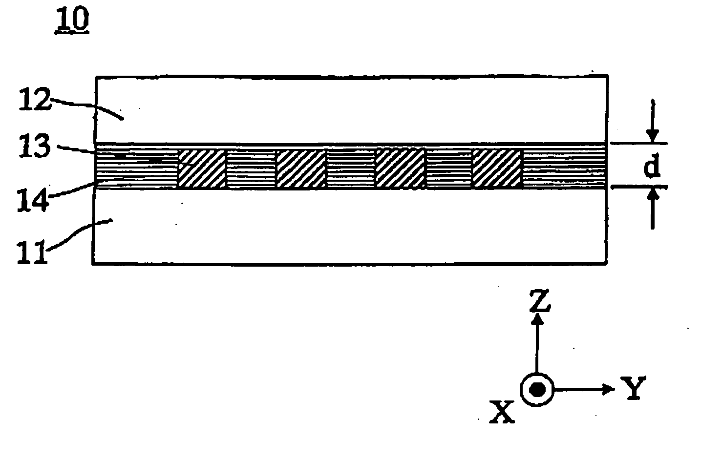
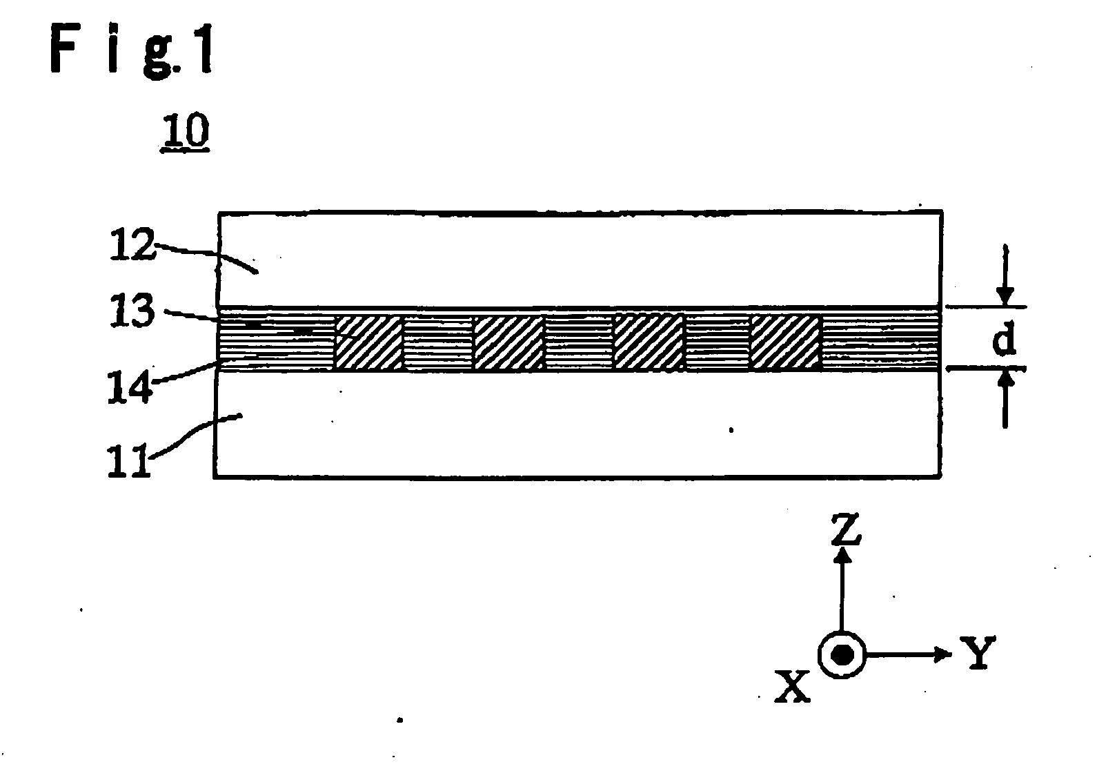
[0082]FIG. 1 shows a cross section of a polarizing diffraction element 10 as a first embodiment of the present invention, comprising transparent substrates 11 and 12, and a grating (hereinafter referred to as “polymer liquid crystal grating”) 13 made of a polymer liquid crystal, and a filler 14, that are provided between the transparent substrates 11 and 12.
[0083] Among these, transparent substrates 11 and 12 are made of a transparent material having uniform refractive index such as a glass.
[0084] Here, a polymer liquid crystal layer of a polymer liquid crystal grating 13, is formed by uniformly applying e.g. a nematic liquid crystal monomer material containing a chiral compound and having an ordinary refractive index no and an extraordinary refractive index ne. By thus containing a chiral compound, it is possible to form a cholesteric phase liquid crystal having a twisted alignment of a spiral structure having a spiral axis in the thickness direction (Z direction) of the liquid c...
second embodiment
[0112] Then, a polarizing diffraction element according to the second embodiment of the present invention is described with reference to a cross-sectional view shown in FIG. 3. Here, in this embodiment, components common with those of the first embodiment, are designated as the same reference numerals to avoid duplication of explanation.
[0113] A polarizing diffraction element 20 according to the second embodiment is different from the element of the first embodiment in that an optically isotropic material is fabricated into a grating (hereinafter, it is referred to as “isotropic grating”) 21 having a concavo-convex shape cross section, and at least concave portions of the grating are filled with a polymer-stabilized blue phase liquid crystal 22 in the polarizing diffraction element 20.
[0114] The isotropic grating 21 may be formed by directly fabricating the surface of a transparent substrate 11, or else, it may be formed by forming an inorganic material film such as SiON or an org...
third embodiment
[0118] Then, a polarizing diffraction element 50 according to a third embodiment of the present invention in which a wavelength selective diffraction element and a phase plate are laminated on the polarizing diffraction element 10 of the first embodiment, is described with reference to the cross-sectional view shown in FIG. 4. Here, also in this embodiment, components in common with those of the first and the second embodiments, are designated as the same reference numerals to avoid duplication of explanation.
[0119] The polarizing diffraction element 50 of this embodiment comprises an optical element (hereinafter, this is referred to as “phase element”) 40 having a phase plate 43 to be described later, a wavelength selective diffraction element 30, and the polarizing diffraction element 10 of the first embodiment, that are integrated together. Here, the wavelength selective diffraction element 30 and the polarizing diffraction element 10, may be hologram beam splitters having a pol...
PUM
 Abstract
Description
Claims
Application Information
 - R&D Engineer
- R&D Manager
- IP Professional
- Industry Leading Data Capabilities
- Powerful AI technology
- Patent DNA Extraction
Browse by: Latest US Patents, China's latest patents, Technical Efficacy Thesaurus, Application Domain, Technology Topic.
© 2024 PatSnap. All rights reserved.Legal|Privacy policy|Modern Slavery Act Transparency Statement|Sitemap