
Intraosseous dental implant

a dental implant and implant technology, applied in dentistry, dental surgery, medical science, etc., can solve the problems of long time of physical and psychological discomfort of patients, and achieve the effect of reducing post-operative discomfort and sufficient immediate stability

Inactive Publication Date: 2006-10-26
C I R G
View PDF6 Cites 22 Cited by
  • Summary
  • Abstract
  • Description
  • Claims
  • Application Information

AI Technical Summary

Benefits of technology

[0006] The healing time is necessary to allow the “osseointegration” of the implant, which means that new alveolar bone forms around the threaded pin, hence giving the implant the necessary stability to stand against the load of the chewing forces.
[0018] This becomes possible because of the specific shape of the threaded pin, which provides sufficient immediate stability once placed in situ. It is therefore possible to assure the patient with the real chance to wear immediately after surgery a fixed provisional prosthesis, apt to chew the food and to perform normal social life.
[0019] The surgical steps are shorted, the post-operative discomfort is reduced.
[0028] It is the cup shaped tissue conditioner that allows to maintain the shape of soft tissues around the implant until the final prosthesis is definitely cemented, and assures the perfect final results of the rehabilitation.
[0034] It is of basic importance for the success of the surgery and the safety of the implant that the operator uses drills matching the shape of the implant but at least 2 mm. shorter than the implant, and manual tapping drills to gain the gap of 2 mm. without damaging the surrounding sensible tissues.

Problems solved by technology

Moreover, the patients must submit themselves to a long period of physical and psychological discomfort before the final result is reached.

Method used


Image

  • Intraosseous dental implant
  • Intraosseous dental implant
  • Intraosseous dental implant

Examples


Embodiment Construction

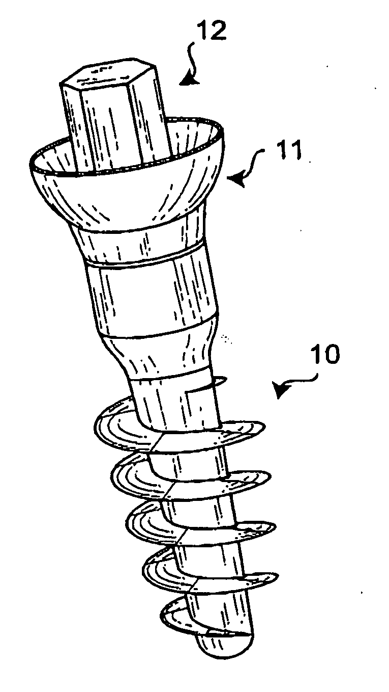
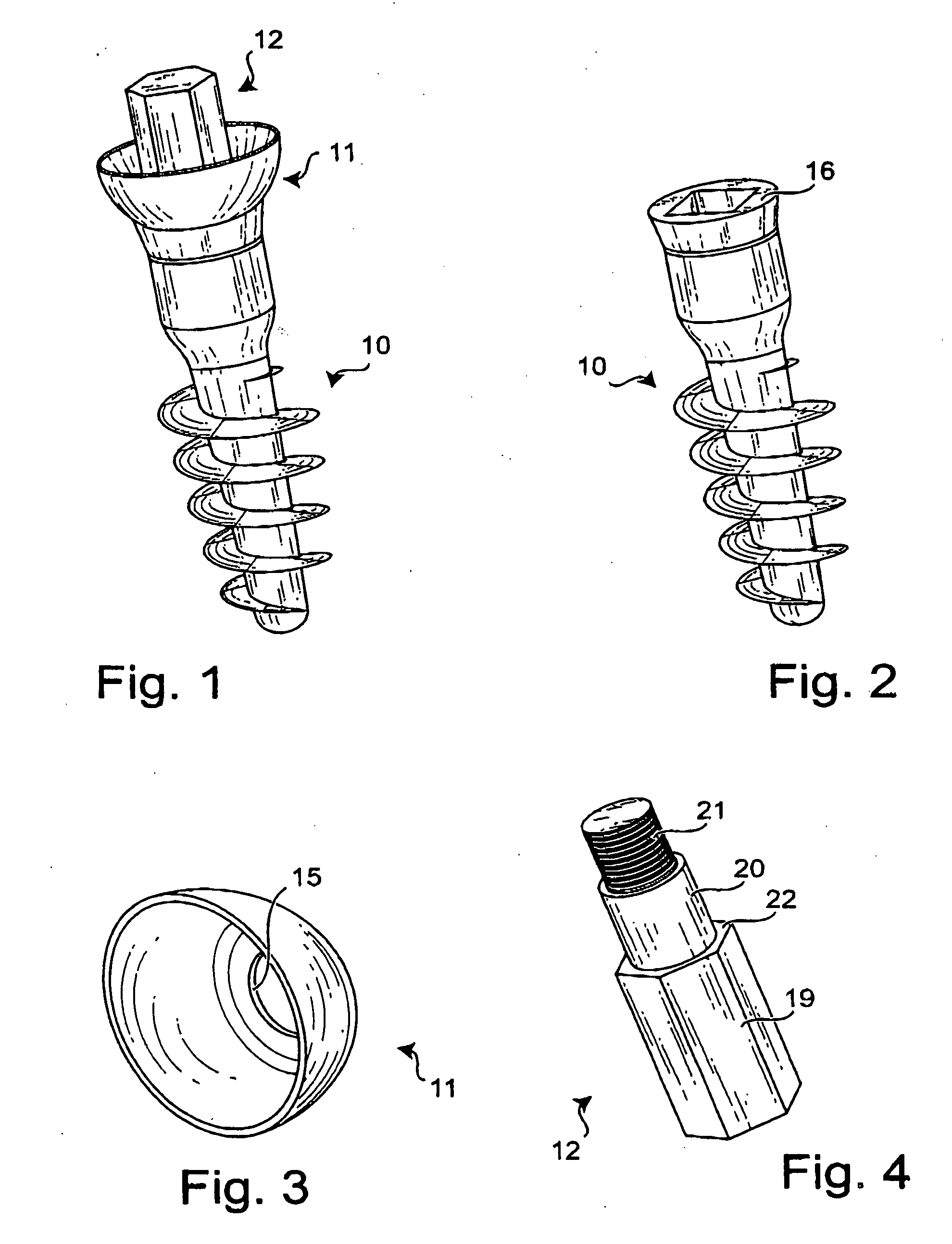
[0042] According to the invention the device is made of three parts which must be assembled together: a threaded pin 10, a hemispheric cup 11, and a locking screw 12.

[0043] The threaded pin 10 is to be screwed into the bone.

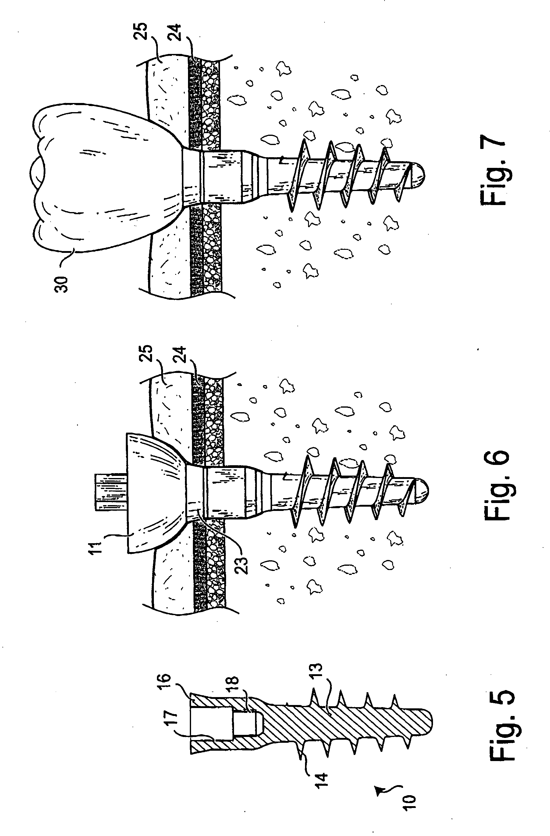
[0044] It must be noted in FIG. 5 the advantage represented by the section of the pin, which decreases as it reaches its apex towards the inner bone structure, both in the core body 13, and in the coil section 14, the coil section keeping a relevant dimension compared to the core body 13.

[0045] Such features allow the threaded pin 10 to be immediately stable against torsional and flexing movements exerted on the pins by chewing loads, so the threaded pin 10 can be used in single-stage surgery as well as in the two-stage surgery.

[0046] Connected to the pin 10 there is a hemispheric cup 11 with a hole 15, which in operative situation lies with the walls of the hole 15 on the top face 16 of the pin 10.

[0047] From the face 16 of the pin 10 a hole extends interna...


PUM


Abstract

Endosseous dental implant of the type involving a threaded pin which is screwed into the bone cavity and is provided with a hole applied to the part of the implant emerging from the bone, housing a proper device protruding from the dental prosthesis in order to anchor the prosthesis to the threaded pin; onto the top part of the threaded pin exceeding the bone a removable hemispheric cup is applied so that when the threaded pin is in final position, the cup presses onto the surrounding gengiva; the cup being equipped with anchoring devices which firmly connect it to the pin, yet allowing it to be unscrewed from the pin in order to be replaced by the dental prosthesis that will fit the place occupied by the cup in the gengiva around the threaded pin.

Description

BACKGROUND OF THE INVENTION [0001] The object of the invention is an endosseous dental implant. [0002] The dental implants actually used possess a threaded pin which is screwed into the bone structure. [0003] Different types of abutments are connected to the pins, emerging through the gingival tissue to anchor the dental prosthesis. [0004] The techniques used to place dental implants are normally either single-stage or two-stage. [0005] The two-stage technique implicates two distinct operative phases. In the first phase the threaded pin is screwed into the bone structure and will remain submerged under the gingival mucosa during the healing period. [0006] The healing time is necessary to allow the “osseointegration” of the implant, which means that new alveolar bone forms around the threaded pin, hence giving the implant the necessary stability to stand against the load of the chewing forces. [0007] Once the appropriate healing time is reached (some months), the top of the pin is ex...

Claims


Application Information

Patent Timeline
IPC IPC(8): A61C8/00
CPCA61C8/0018A61C8/0028A61C8/006A61C8/0054A61C8/005A61C8/0022
Inventor GATTI, CLAUDIO
Owner C I R G
Learn More