Center locking cross-connector with eccentric cam rod engagement

a technology of eccentric cam rod and center locking, which is applied in the direction of prosthesis, instruments, gearing, etc., can solve the problems of early failure of rods or fastener elements, and achieve the effect of optimizing load distribution and minimizing stress concentration

Inactive Publication Date: 2006-10-26
ALTUS PARTNERS
View PDF7 Cites 68 Cited by
  • Summary
  • Abstract
  • Description
  • Claims
  • Application Information

AI Technical Summary

Benefits of technology

[0006] The present invention is directed to a cross-connector system for connecting two rods of an implantable vertebral rod system of a known type, wherein the cross-connector system of the present invention utilizes relatively low-stress concentration contact areas between the connector elements and the rods. In a preferred embodiment, the cross-connector...

Problems solved by technology

Prior art systems of the type illustrated in FIG. 1 have undesirable properties including high stress concentrations at the con...

Method used


Image

  • Center locking cross-connector with eccentric cam rod engagement
  • Center locking cross-connector with eccentric cam rod engagement
  • Center locking cross-connector with eccentric cam rod engagement

Examples


Embodiment Construction

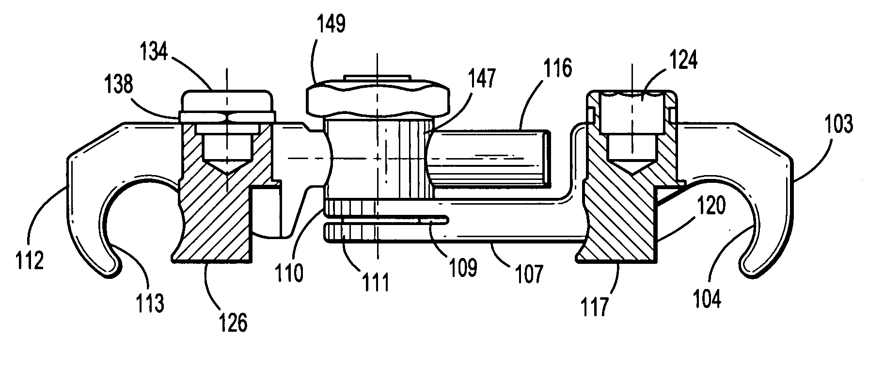
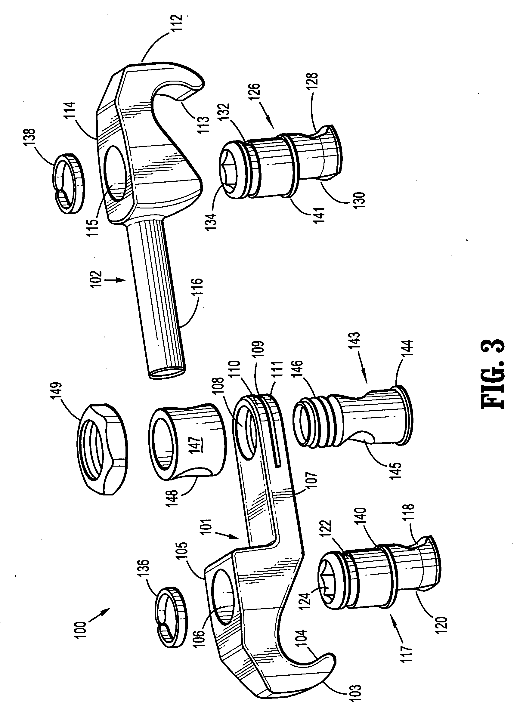
[0015] A first embodiment of the present invention is shown in FIGS. 2A-4D. According to the present invention, a cross-connector system (102) includes a first member (101) and a second member (102). The first member (101) comprises: a hook end (103) having in inner, curved rod-engagement surface (104); a cam-retaining section (105) with a hole (106) therethrough; and an arm section (107) having a hole (108) therethrough and a slot (109) forming two flexible end portions (110, 111). The second member (102) comprises: a hook end (112) having in inner, curved rod-engagement surface (113); a cam-retaining section (114) with a hole (115) therethrough; and an arm section (116) formed in the shape of a rounded rod. The system (100) further includes a first cam plug (117) having a curved, rod-engaging surface (118), an opposite non-engaging surface (120), a snap-ring channel (122), a flange (140), and a torque tool engaging section (124). Similarly, a second cam plug (126) has a curved, ro...


PUM


Abstract

A cross-connector system for connecting two rods of an implantable vertebral rod system utilizes relatively low-stress concentration contact areas between the connector elements and the rods. The cross-connector system includes a two-piece, elongated member (100) that is adjustable lengthwise and has, at each end, hook-shaped ends (103, 112) which each cooperate with a rotatable, eccentric cam plug (117, 126) having a curved surface (118, 128) that engages and secures a rod to the hook-shaped end in a manner that optimally distributes load to minimize stress concentrations.

Description

RELATED APPLICATIONS [0001] This application is related to and claims priority from U.S. Provisional Patent Application 60 / 659,241, file on Mar. 7, 2005.TECHNICAL FIELD [0002] The present invention relates to surgically implanted devices and, more particularly, implantable devices for vertebral repair or reconstruction comprising cross-connectors for rod constructs. BACKGROUND OF THE INVENTION [0003] Various known techniques and systems exist for repairing or reconstructing injured or diseased vertebral sections in which one or more implants are provided in or adjacent to a vertebral disc space in a manner in which two or more adjacent vertebrae are stabilized relative to each other or are fused together. Such a solution provides stability and pain relief. It is known to use rod systems that generally comprise one or more metal rods that each span a gap between at least two adjacent vertebrae, wherein the rod is fixed to the adjacent vertebrae by bone screws or fasteners inserted di...

Claims


Application Information

Patent Timeline
IPC IPC(8): A61F2/30
CPCY10T74/22A61B17/7052
Inventor KHALILI, FARID BRUCE
Owner ALTUS PARTNERS
Why Eureka
Try Eureka