Intervertebral implant devices for supporting vertebrae and devices and methods for insertion thereof

a technology of intervertebral implants and supporting vertebrae, which is applied in the direction of spinal implants, joint implants, prostheses, etc., can solve the problems of disc bulging or herniation, subsequent disc structural failure, back pain, etc., and achieves the optimization of device and material physical characteristics, less ductility, and minimize stress concentration in the implant body

Inactive Publication Date: 2013-06-25
PIONEER SURGICAL TECH INC
View PDF86 Cites 6 Cited by
  • Summary
  • Abstract
  • Description
  • Claims
  • Application Information

AI Technical Summary

Benefits of technology

[0010]In accordance with one aspect of the invention, an implant device for implantation within an intervertebral space between adjacent vertebrae is provided. The implant device includes an implant body preferably formed of a synthetic bone substitute material that is desirably bioresorbable and osteoconductive, but is less ductile than materials typically used for intervertebral implants (such as PEEK, for example). Hence, the implant body and the methods and tools for implanting the device are configured to optimize the physical characteristics of the device and the material used and minimize stress concentration in the implant body.
[0011]In one form, the implant body has a smooth, continuous annular wall defining an inner void and vertebral body gripping structure configured for minimizing locations of stress concentration in the implant body. This allows for optimized strength and stability while also promoting bone growth through the implant body and fusion of the vertebrae. With the smooth, continuous annular wall, the implant body lacks any openings, throughbores, channels, cut-outs, and / or sharp corners therein that can provide areas on the implant body in which stress may be concentrated. Preferably, the only opening in the implant body is the inner void or throughbore that extends through the implant body along a central axis that is generally aligned with the compressive forces that the implant will bear once inserted between adjacent vertebrae.

Problems solved by technology

Typically, the patients' intervertebral discs, which support the spine, are damaged, causing the discs to bulge or herniate.
The disc bulge then impinges on the nerves of the spine and cause back pain.
However, the discectomy may structurally weaken the disc and often leads to subsequent structural failure of the disc due to wear and aging, once again causing impingement on the nerves of the spine and cause back pain.
While natural bone implants advantageously promote bone growth and fusion at the implant site, the use of natural bone can be problematic because of the potential for structural failure of the implant, rejection of the implant by the patient, and the risk of infection.
In particular, failure of the bone graft implant may be caused by non-viability of the bone graft material, which allows for accumulation of structural micro-damage.
Failure of the implant can also result from rejection of the implant by the patient's immune system.
In addition, the risk of infection from cadaver bone creates many attendant costs of mitigation.
The potential for implant failure, rejection, and / or infection may necessitate numerous painful revision surgeries.
In this regard, during VBR insertion there generally are very high forces generated at the interface between the engagement members of the insertion tool and the surfaces about the VBR body openings in which the engagement members are fit.
However, such materials are not bioresorbable and do not allow bone growth through the implant body itself.
However, because such calcium phosphate bioceramic implants have low reliability under tensile loads, such materials have generally only been used as powders, or as small, unloaded implants such as in the middle ear, dental implants with reinforcing metal posts, coatings on metal implants, low-loaded porous implants where bone growth acts as a reinforcing phase, and as the bioactive phase in a composite implant.

Method used


Image

  • Intervertebral implant devices for supporting vertebrae and devices and methods for insertion thereof
  • Intervertebral implant devices for supporting vertebrae and devices and methods for insertion thereof
  • Intervertebral implant devices for supporting vertebrae and devices and methods for insertion thereof

Examples


Embodiment Construction

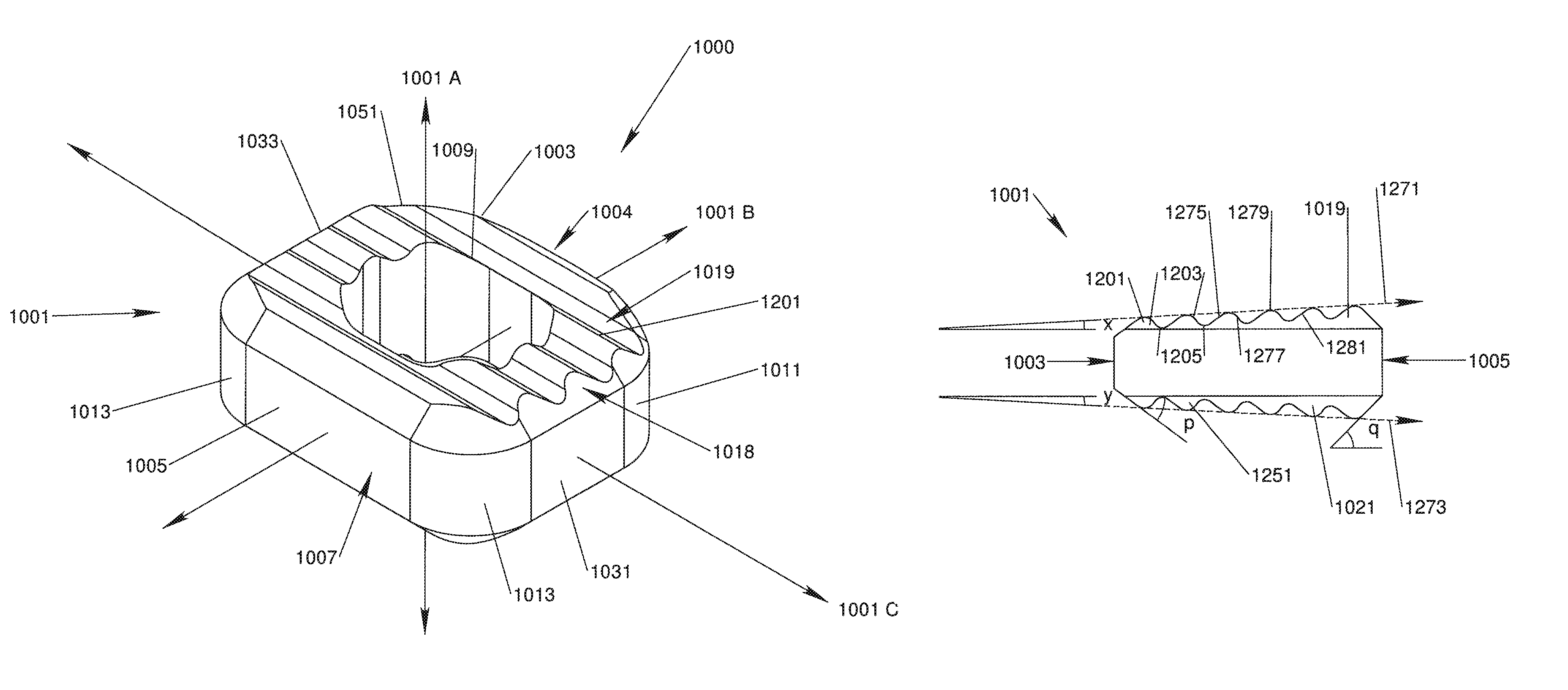
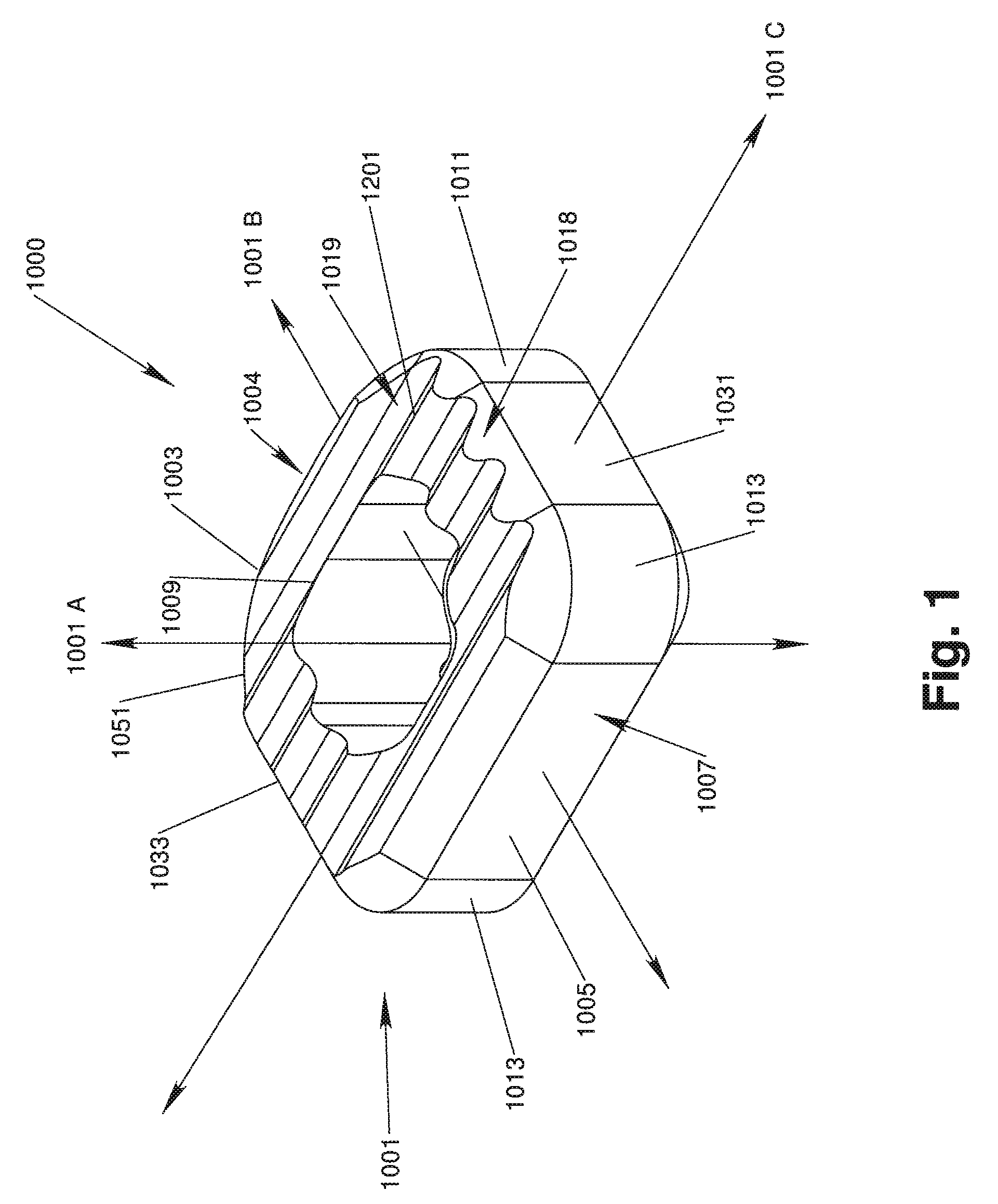
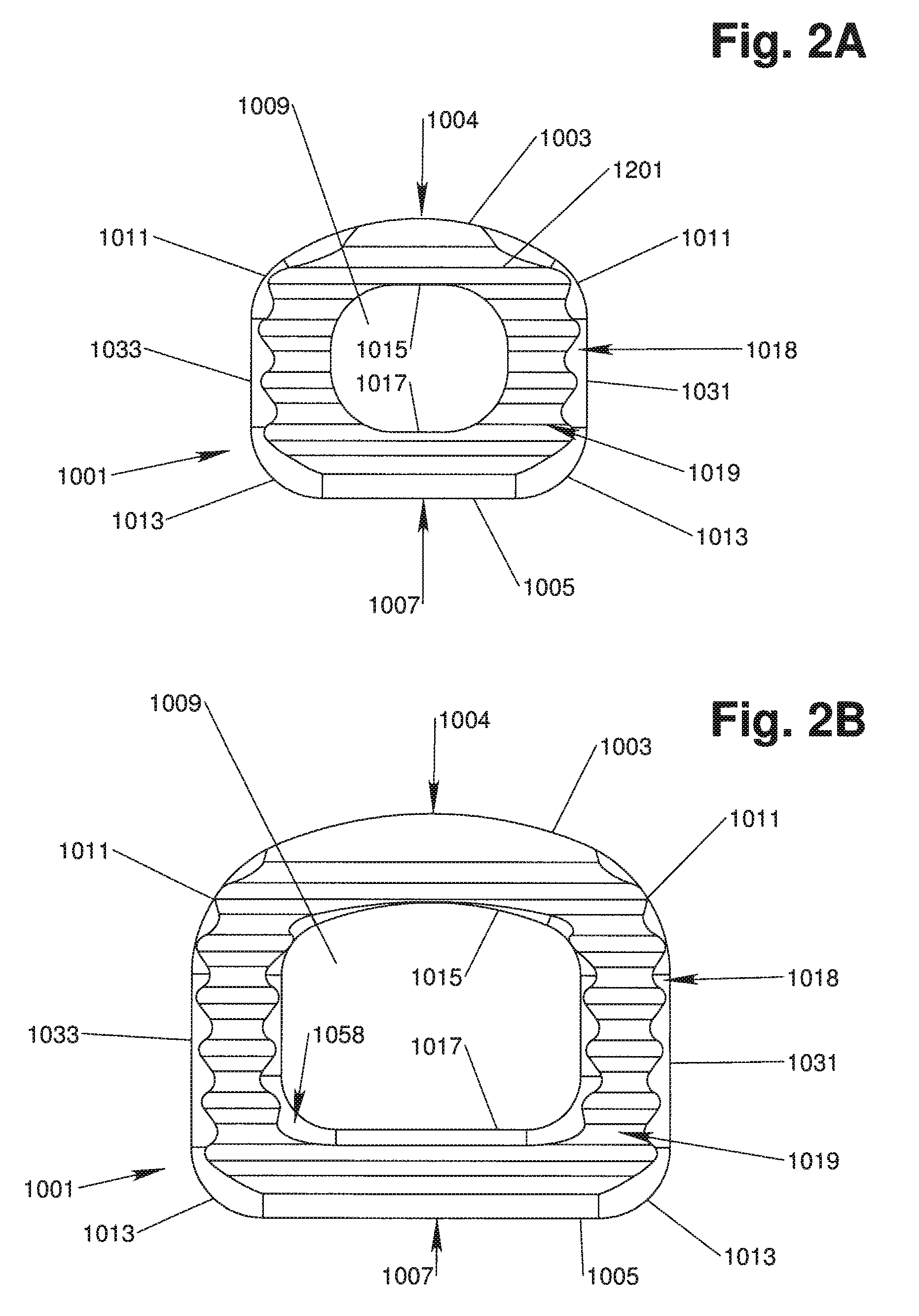
[0039]With reference to FIGS. 1, 2A, 2B, 3, 4, 5A and 5B, in accordance with one aspect of the invention, an implant device 1000 has an implant body 1001 that is configured to be implanted in the intervertebral space between adjacent vertebrae. The implant body 1001 preferably has a generally rectangle-shaped, annular wall 1051 including an anterior wall portion 1005, a posterior wall portion 1003, and opposing side wall portions 1031, 1033. The annular wall 1051 defines upper and lower vertebral engaging surfaces 1019, 1021 and is disposed about a central void or throughbore 1009 extending therebetween, the throughbore 1009 being configured for accepting biologic materials, such as bone graft and / or bone void fillers therein.

[0040]A vertical axis 1001A of the implant body 1001 extends through the upper and lower vertebral engaging surfaces 1019, 1021, generally parallel to the throughbore 1009. An anterior-posterior axis 1001B of the implant body 1001 extends through the center of ...


PUM

PropertyMeasurementUnit
heightaaaaaaaaaa
compressive strengthaaaaaaaaaa

Abstract

Implant devices for implantation within an intervertebral space are provided, together with methods and tools for use therewith. Implant devices of the present invention include an implant body formed of a synthetic bone substitute material, such as a nanocrystalline calcium phosphate material. The implant body and the methods and tools used therewith are configured to optimize strength and stability of the implant, minimize areas of stress concentration in the implant body and promote bone growth through the implant body and fusion of the vertebra.

Description

CROSS-REFERENCE TO RELATED APPLICATIONS[0001]This application claims the benefit of the filing date of U.S. Provisional Application No. 61 / 041,893, filed on Apr. 2, 2008, and U.S. Provisional Application No. 61 / 042,139, filed on Apr. 3, 2008, which are hereby incorporated in their entirety herein.FIELD OF THE INVENTION[0002]This invention pertains generally to implantable medical devices and, in particular, to implantable devices for intervertebral fusion and / or immobilization.BACKGROUND OF THE INVENTION[0003]Many people develop back pain during the course of their life due to traumatic injury, disease, or genetic defect. Typically, the patients' intervertebral discs, which support the spine, are damaged, causing the discs to bulge or herniate. The disc bulge then impinges on the nerves of the spine and cause back pain. Surgeons often perform a discectomy to trim the disc bulge to alleviate back pain. However, the discectomy may structurally weaken the disc and often leads to subseq...

Claims


Application Information

Patent Timeline
Patent Type & Authority Patents(United States)
IPC IPC(8): A61F2/44A61F2/46
CPCA61F2/4611A61F2/4684A61L27/12A61F2/4465A61F2/447A61F2/30965A61F2002/30828A61F2002/2817A61F2002/30062A61F2002/30266A61F2002/30677A61F2002/30892A61F2002/30968A61F2002/3097A61F2002/4627A61F2002/4628A61F2002/4629A61F2210/0004A61F2230/0082A61F2310/00023A61F2310/00796A61L2400/12A61L2430/38A61F2310/00293A61F2002/30136A61F2002/4475A61F2002/30593
Inventor KOVARIK, JOHNROGERS, ALLISONBARRON, KATIE S.MACMILLAN, ADAM
Owner PIONEER SURGICAL TECH INC
Why Eureka
Try Eureka