
Fatigue load resistant structures and welding processes

a technology of fatigue load and fatigue loading, applied in the direction of machine/engine, manufacturing tools, welding apparatus, etc., can solve the problems of fatigue load structures or parts of structures subjected to numerous physical forces, tensile and compressive forces can form cracks, and the weight of housing or nacelle is significant, so as to reduce retard the formation of cracks, and eliminate the effect of welding

Inactive Publication Date: 2011-07-07
GENERAL ELECTRIC CO
View PDF31 Cites 0 Cited by
  • Summary
  • Abstract
  • Description
  • Claims
  • Application Information

AI Technical Summary

Benefits of technology

[0006]An exemplary embodiment includes a fatigue load resistant structure including a fatigue loaded portion and a weldable fatigue loading resistant feature. The fatigue loaded portion includes a first elongation material. The weldable fatigue loading resistant feature includes a second elongation material secured to the fatigue loaded portion of the fatigue loaded structure. In the embodiment, the first elongation material is less ductile than the second elongation material, and the weldable fatigue loading resistant feature reduces, retards, or eliminates formation of cracks due to tensile and compressive forces.
[0007]Another exemplary embodiment includes a welding process for welding a fatigue load resistant structure including identifying a fatigue loaded portion of the fatigue loaded structure and selecting the weldable fatigue loading resistant feature. The fatigue loaded portion includes a first elongation material. The weldable fatigue loading resistant feature includes a second elongation material. The first elongation material is less ductile than the second elongation material. In the embodiment, securing the weldable fatigue loading resistant feature to the fatigue loaded portion of the fatigue loaded structure reduces, retards, or eliminates formation of cracks due to tensile and compressive forces.
[0008]Another exemplary embodiment includes a fatigue load resistant structure including a fatigue loaded portion of the fatigue loaded structure and a weldable fatigue loading resistant feature. The fatigue loaded portion includes a first elongation material. The weldable fatigue loading resistant feature includes a second elongation material secured to the fatigue loaded portion of the fatigue loaded structure. In the embodiment, the first elongation material is less ductile than the second elongation material. The first elongation material is a low alloy steel or carbon steel. The second elongation material is a nickel-based alloy. Also, the weldable fatigue loading resistant feature reduces, retards, or eliminates formation of cracks due to tensile and compressive forces.

Problems solved by technology

The housing or nacelle has significant mass which is fatigue loaded on the tower or base.
Movement of the housing due to wind or other forces may result in loads such as reversing fatigue loads on the tower or base or on the nacelle or the housing.
Fatigue loaded structures or portions of structures may be subjected to numerous physical forces.
Over time, the tensile and compressive forces can form cracks.
Ultimately, the cracks can lead to failure of the structure.
Welds formed by carbon and low alloy steels can crack upon fatigues loading, depending on the amount of strain, number of cycles and the environment they are in.
The frames and / or other suitable articles can be expensive and / or take substantial time to install.
Furthermore, the frames and / or other suitable articles can still be susceptible to failure after being formed in compliance with standard D1.5, due to excessive loading conditions.

Method used


Image

  • Fatigue load resistant structures and welding processes
  • Fatigue load resistant structures and welding processes
  • Fatigue load resistant structures and welding processes

Examples


Embodiment Construction

[0014]Provided is a mechanism for reducing, retarding, and / or eliminating cracks and the propagation of cracks in fatigue loaded structures to form a fatigue load resistant structure. Embodiments of the present disclosure include improved resistance to structural failure, prolonged life for structures, and / or increased elongation for fatigue loaded portions of fatigue loaded structures.

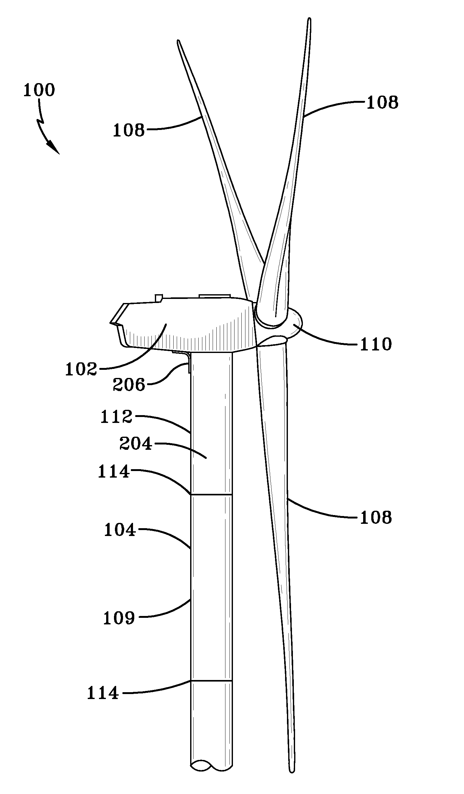
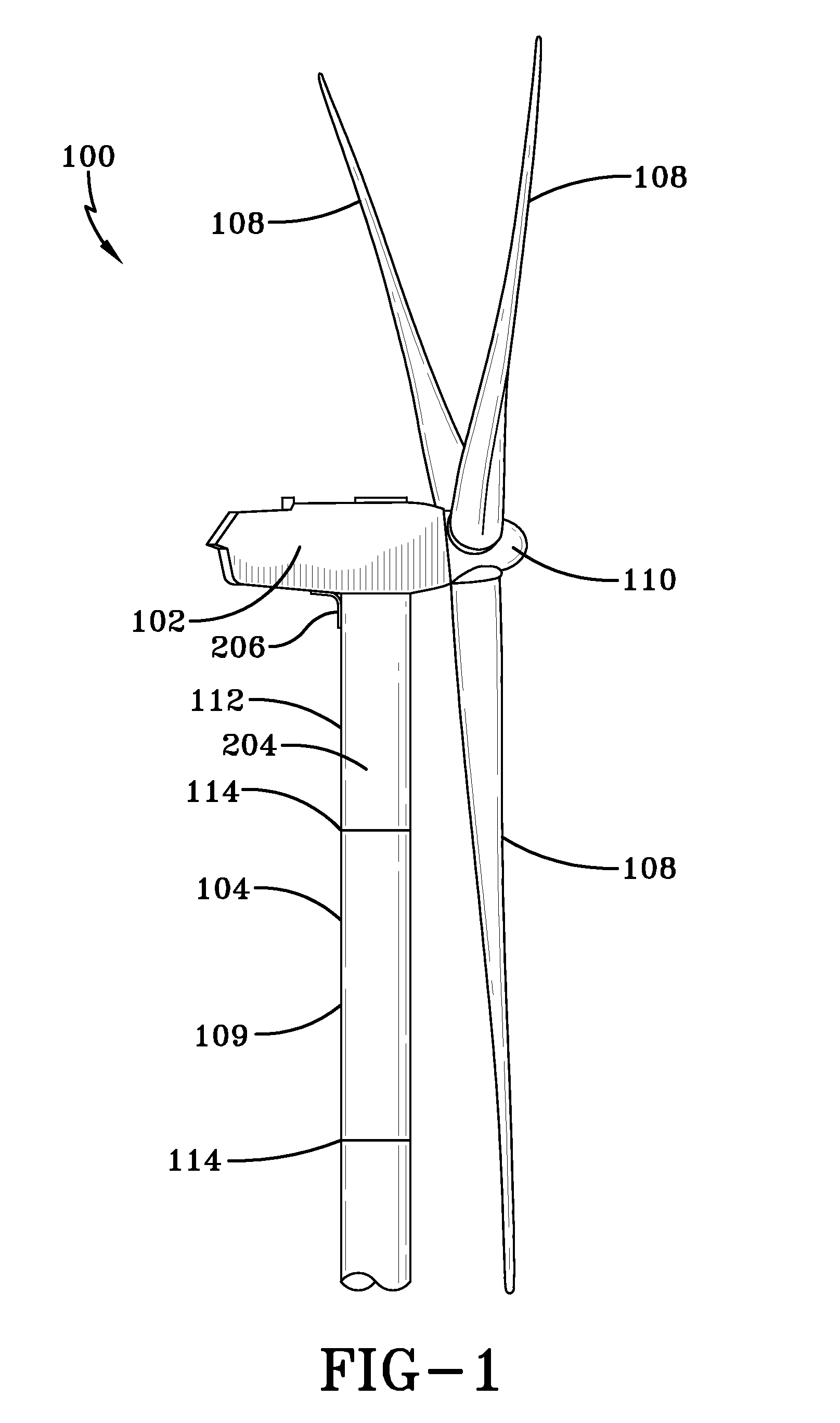
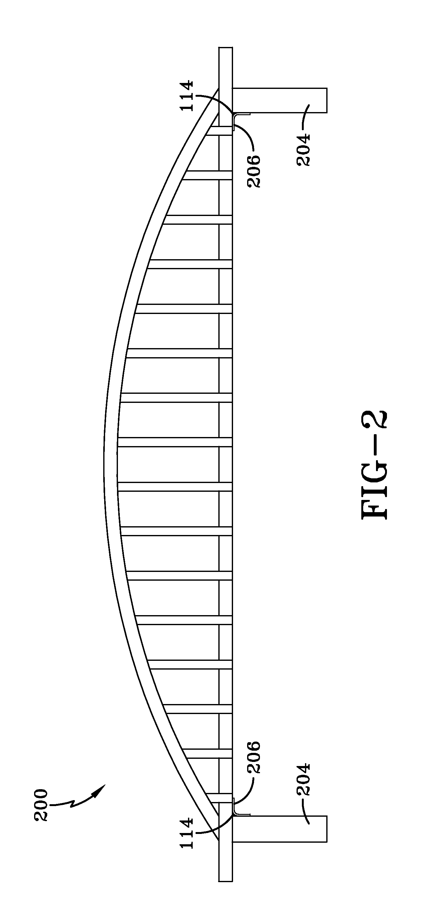
[0015]FIG. 1 shows an exemplary fatigue loaded structure being a wind turbine system 100. Wind turbine system 100 generally comprises a nacelle 102 housing a generator (not shown). Nacelle 102 can be a housing mounted atop a tower 104. Tower 104 can include a first portion 109 and a second portion 112 welded or bolted together at joint 114. In one embodiment, the tower may further include another bolted joint securing second portion 112 to nacelle 102 and allowing nacelle 102 to rotate. In addition, tower can further include another weld securing second portion 112 to nacelle 102. Wind turbine system ...


PUM

PropertyMeasurementUnit
yield strengthaaaaaaaaaa
elongationaaaaaaaaaa

Abstract

A fatigue load resistant structure includes a fatigue loaded portion and a weldable fatigue loading resistant feature. The fatigue loaded portion includes a first elongation material. The weldable fatigue loading resistant feature includes a second elongation material secured to the fatigue loaded portion of the fatigue loaded structure. The first elongation material is less ductile than the second elongation material, and the weldable fatigue loading resistant feature can reduce, retard, or eliminate formation of cracks due to tensile and compressive forces.

Description

FIELD OF THE INVENTION[0001]The present disclosure generally relates to weld structures and welding processes. In particular, the present disclosure relates to welded structures including high elongation material to reduce, retard, or eliminate the formation of cracks due to tensile and / or compressive forces from fatigue loading.BACKGROUND OF THE INVENTION[0002]Structures and articles are continuously being designed and produced to be larger, to be more complex, and to have increased strength. One such structure is a wind turbine. Wind turbines can include a plurality of blades rotationally coupled to a generator rotor through a hub. The generator rotor can be mounted within a housing or nacelle, which may be positioned on top of a tubular tower or a base. The housing or nacelle has significant mass which is fatigue loaded on the tower or base. Movement of the housing due to wind or other forces may result in loads such as reversing fatigue loads on the tower or base or on the nacel...

Claims


Application Information

Patent Timeline
Patent Type & Authority Applications(United States)
IPC IPC(8): F03D11/04B32B7/02B23K31/02
CPCB23K31/00Y02B10/30Y02E10/726Y02E10/728Y10T403/4602Y10T403/42Y10T428/24983Y10T428/12986Y10T403/477Y02E10/72F16B2200/67
Inventor NOWAK, DANIEL ANTHONYKOTTILINGAM, SRIKANTH CHANDRUDYJOHNSTON, BILL DAMON
Owner GENERAL ELECTRIC CO
Learn More