Networked leak and overflow detection, control and prevention system

a leak detection and leak prevention technology, applied in water installations, instruments, constructions, etc., can solve the problems of difficult installation, difficult installation, inability to work in toilets and urinals, etc., to increase the signal to noise ratio, effectively power devices and assemblies, and low current cost of microcontrollers.

Inactive Publication Date: 2016-11-10
VISWANATHAN MAHESH
View PDF3 Cites 5 Cited by
  • Summary
  • Abstract
  • Description
  • Claims
  • Application Information

AI Technical Summary

Benefits of technology

[0015]The present invention provides an improvement over leak detection devices of the prior art by using fewer components. For example, the current cost of microcontrollers is very low, costing just a few dollars. Thus, an object of this invention is to use as few discrete components as possible, for example, by using a single module SOC (system-on-chip) that includes a microcontroller with an operating system, volatile (RAM) and non-volatile (flash) memories, Wi-Fi, LED, LDR and multiple digital I/O pins and analog inputs, with the complete module currently retail priced at around $4. The SOC module provides the electronic components and electrical connection points for the sensors and sensor assemblies installed in and around the toilet. The SOC module also removes requirements for discrete components and manufacturing steps for example, by tying an input pin high removes the need for a pull-up resistor. The SOC module software and algorithms increase the signal to noise S/N ratio of sensors whenever possible, rather than using an amplifier circuit that would require additional components. The SOC module within the leak and overflow and prevention system also provides for components to have multiple functions. For example, the LED may function as both a visual indicator and as a proximity detector in the same circuit. As a proximity detector, the LED, when reverse-biased, functions as a photodiode and the charge it holds in this state is released as a photocurrent during forward-bias. By measuring the time taken to discharge the level of ambient light can be construed and changes within the time taken for discharge may indicate human motion in the vicinity of the toilet.
[0016]Another object of the present invention is the capability to run the leak detector and/or sensor assemblies on battery, solar cells or connected to t

Problems solved by technology

However, they are generally unable to work in toilets and urinals that do not have a tank or an exposed tank and are generally also harder to install, i.e. to add-on to an existing fixture.
These devices take sensor readings from inside the tank, which is harder to install or by measuring the vibration of the tank to detect errant operation, which is too indirect and lacks the nuance to detect almost imperceptible flows as they occur.
While some of the leak detectors of

Method used


Image

  • Networked leak and overflow detection, control and prevention system
  • Networked leak and overflow detection, control and prevention system
  • Networked leak and overflow detection, control and prevention system

Examples


Embodiment Construction

[0062]The following description is provided to enable any person skilled in the art to make and use the invention and sets forth the best modes contemplated by the inventors of carrying out their invention. Various modifications, however, will remain readily apparent to those skilled in the art, since the generic principles of the present invention have been defined herein specifically to provide for an improved and simplified leak detection and overflow detection and prevention system.

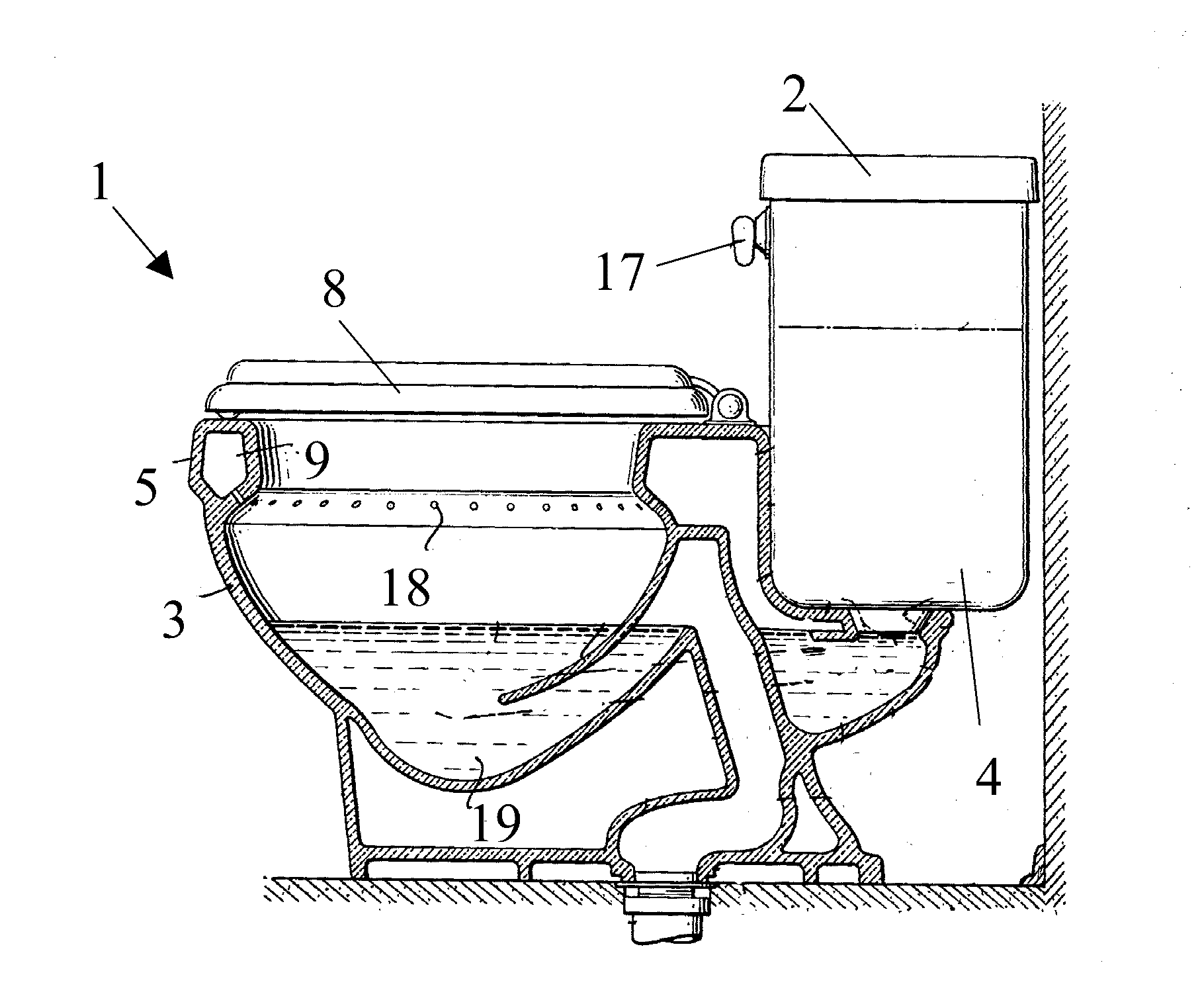
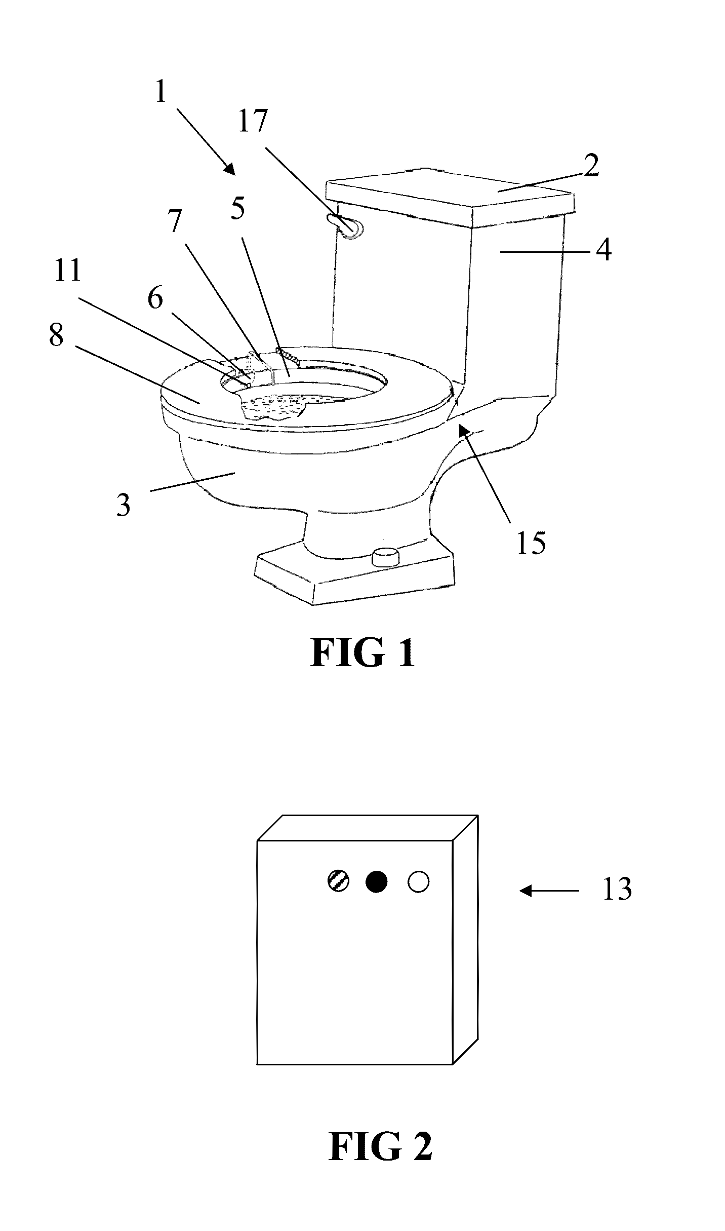
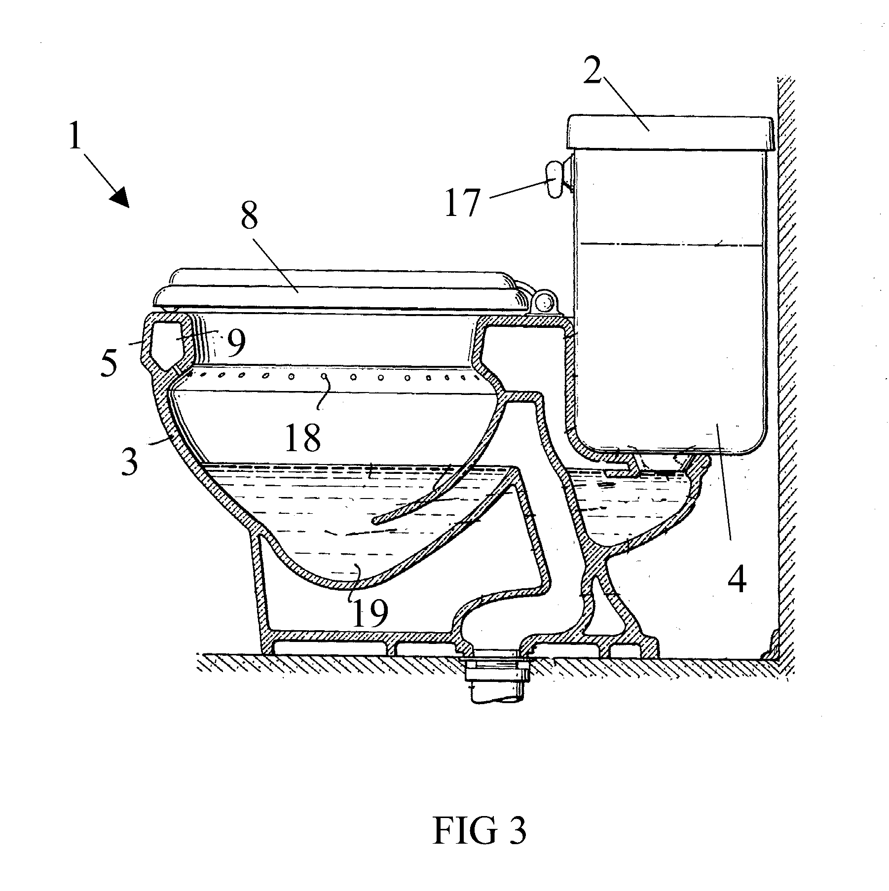
[0063]As shown in FIG. 1, embodiments of the leak and overflow and prevention system has one or more leak detectors, sensor assemblies and other devices located within the vicinity of the toilet 4 being monitored for leaks. A particular embodiment of a leak detector device 6 of the present invention is shown mounted off to the side of the bowl 3 of the toilet 1 suspended from the upper rim 5 of the toilet bowl 3 using a wire hook 7 as shown through a cut-out of the seat 8. While detection devices of t...


PUM


Abstract

A microprocessor-operated, networked device that uses sensors in, on and near the toilet to detects toilet leaks and overflows of the toilet tank or bowl, then reports these errant conditions with a visual or audible indicator in addition to sending a message via a network (if available) to a computer system that may collate this data with that from other toilets and other sources and subsequently determine further action such as shutting off water or calling a technician. The present invention can be integral to a toilet or removably attached to an existing toilet without this technology.

Description

RELATED APPLICATION[0001]This application claims the benefit of U.S. Provisional Application No. 62 / 159,350 filed May 10, 2015 and entitled EXTENSIBLE NETWORKED FLUID LEAK DETECTION SYSTEM, which is hereby incorporated herein by reference in its entirety.FIELD OF THE INVENTION[0002]This invention relates generally to fluid detection devices and more particularly to devices for alleviating toilet water leaks into the bowl and for detecting overflows from the flush tank or the bowl.BACKGROUND OF THE INVENTION[0003]Leaky toilets are the single largest waste of water indoors, a problem that the present invention addresses. Many patents teach mechanical and electrically operated water leak and overflow detection and overflow control devices to detect and selectively prevent the leak and overflowing of toilets. However, they are generally unable to work in toilets and urinals that do not have a tank or an exposed tank and are generally also harder to install, i.e. to add-on to an existing...

Claims


Application Information

Patent Timeline
IPC IPC(8): G08B29/18G08B21/20H04L29/08G08B21/18E03D11/00E03D1/00
CPCG08B29/185E03D11/00G08B21/20H04L67/125G08B21/182E03D1/00Y02A10/30
Inventor VISWANATHAN, MAHESH
Owner VISWANATHAN MAHESH
Why Eureka
Try Eureka