Guide loops for a seat belt system

a seat belt and loop technology, applied in the field of seat belt systems, can solve the problems of increasing vehicle manufacturing costs, affecting vehicle trim design, and increasing rattle during vehicle operation, so as to improve comfort, reduce friction, and maximize occupant comfort

Inactive Publication Date: 2011-03-17
GM GLOBAL TECH OPERATIONS LLC
View PDF62 Cites 6 Cited by
  • Summary
  • Abstract
  • Description
  • Claims
  • Application Information

AI Technical Summary

Benefits of technology

[0007]The guide loops are not rotatable with respect to the body of the vehicle and / or the body of the height adjuster of the vehicle. However, the guide loops nonetheless maximize and improve occupant comfort while allowing for decreased friction between the guide loops and the seat belt webbing during refraction and / or extraction of the seat belt webbing. Therefore, the guide loops, with such improved comfort, encourage seat belt use by a vehicle occupant. The guide loops also optimize controlled retraction and / or extraction of the seat belt webbing, and allow the seat belt webbing to optimally distribute loads during load limiting events, such as a deceleration of the vehicle. Further, the guide loops allow for excellent closure to the trim of the vehicle, resist rattle during operation of the vehicle, and reduce vehicle manufacturing costs.

Problems solved by technology

Rotatable guide loops also often require a large guide loop profile, which may affect vehicle trim design.
Further, rotatable guide loops often include multiple components, and may contribute to increased vehicle manufacturing costs and increased rattle during operation of the vehicle.

Method used


Image

  • Guide loops for a seat belt system
  • Guide loops for a seat belt system
  • Guide loops for a seat belt system

Examples


first embodiment

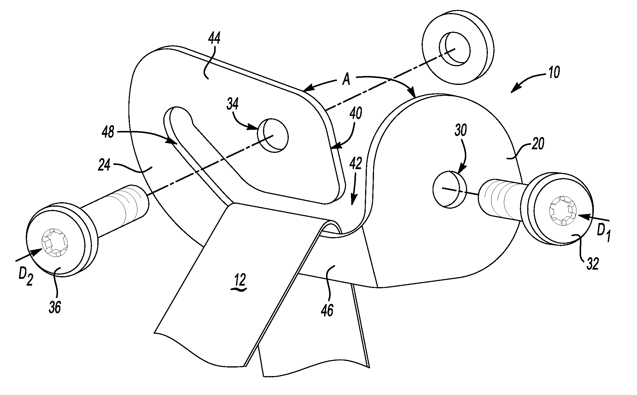
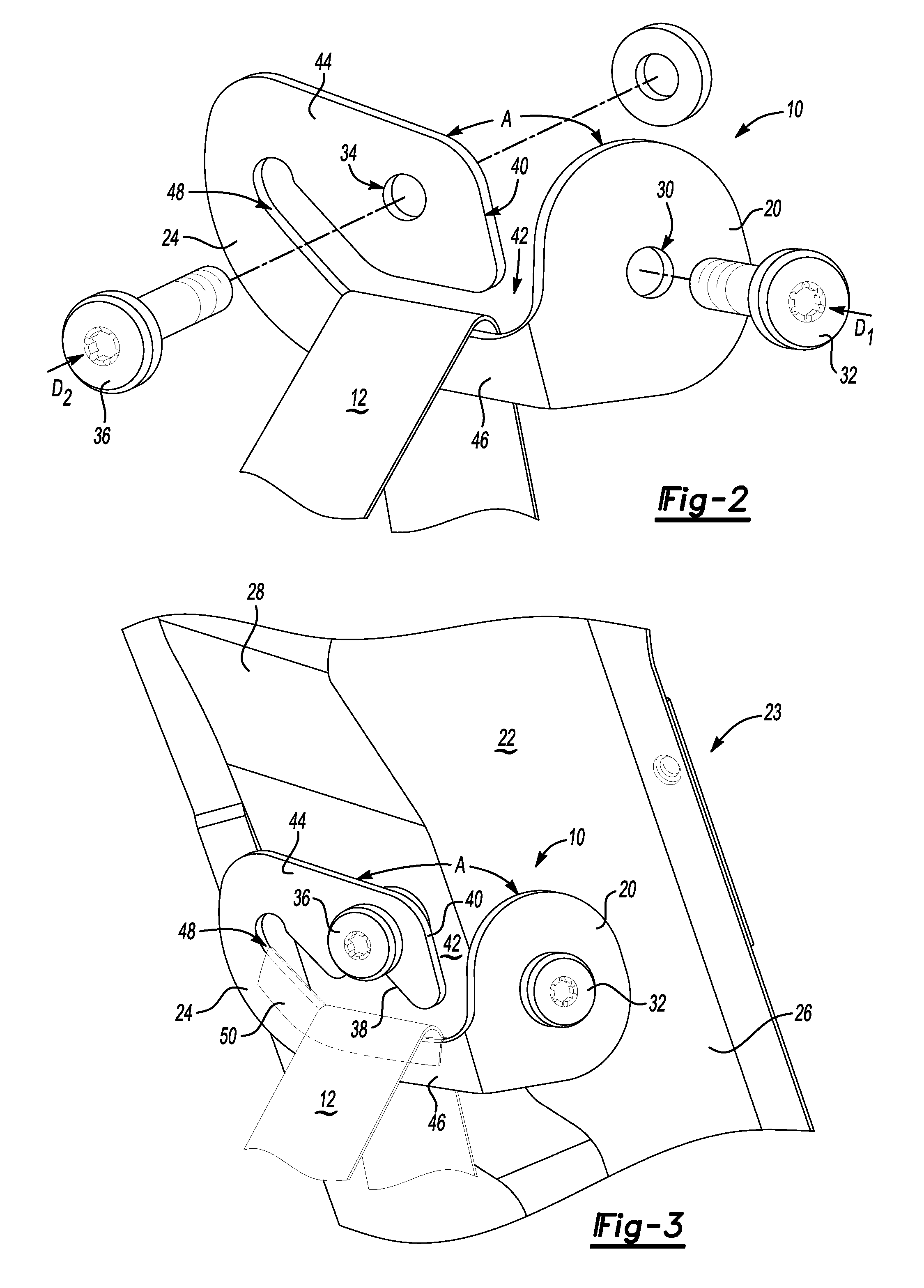
[0019]Referring now to FIGS. 2 and 3, a guide loop 10, which may also be known as a D-ring or turning loop, includes a first portion 20 configured for attachment to a body or pillar 22 (FIG. 3) of a vehicle 23 (FIG. 3) in one plane, and a second portion 24 extending from the first portion 20 at an angle, A, and configured for attachment to the body or pillar 22 (FIG. 3) of the vehicle 23 (FIG. 3) in another plane. That is, referring to FIGS. 2 and 3, one plane may be generally perpendicular to one direction, indicated by arrow D1 in FIG. 2, and another plane may be generally perpendicular to another direction, indicated by arrow D2 in FIG. 2. Further, the first portion 20 may be integral with the second portion 24 and may be configured to abut the body 22. For example, the first portion 20 may be crimped, e.g., bent, at the angle, A, to form the second portion 24. Referring to FIG. 3, the angle, A, may be selected according to a configuration of the body or pillar 22 of the vehicle ...

second embodiment

[0028]Referring now to FIG. 4, a guide loop is shown generally at 110. For this embodiment, the guide loop 110 also includes a first portion 20 configured for attachment to the body or pillar 22 of the vehicle 23. The guide loop 110 also includes a second portion 24 extending from the first portion 20 at the angle, A, and configured for attachment to the body or pillar 22 of the vehicle 23.

[0029]Referring to FIG. 4, the guide loop 110 additionally includes a third portion 52 extending from the second portion 24 and substantially parallel to the first portion 20. Therefore, referring to FIG. 5, it is to be appreciated that the third portion 52 also extends from the second portion 24 at approximately the angle, A. As set forth above, the first portion 20 may be integral with the second portion 24 and crimped, e.g., bent, at the angle, A. Likewise, the second portion 24 may be integral with the third portion 52 and also crimped at the angle, A. Therefore, the second portion 24 may be i...

third embodiment

[0036]In a third embodiment, a guide loop 210 for a vehicle (not shown) having a seat belt system including a height adjuster 58 is shown in FIGS. 6-8, wherein the body of the vehicle is the height adjuster 58. By way of general background explanation and with reference to FIGS. 7 and 8, the height adjuster 58 typically includes one portion as a carriage 60 that is configured to vertically translate along another portion as a rail 62 that is anchored to the vehicle 23 (FIG. 3). In operation, an occupant of the vehicle 23 (FIG. 3) may adjust the height of the guide loop 210 by using the height adjuster 58 according to comfort preferences.

[0037]Referring to FIG. 6, the guide loop 210 includes a loop portion 64 configured for receiving and slideably supporting the seat belt webbing 12 (FIG. 7). That is, referring to FIG. 8, the loop portion 64 may define the arcuate bearing surface 48 that is configured for slideably supporting the seat belt webbing 12. And, as set forth above, the arc...


PUM


Abstract

A guide loop for a vehicle seat belt system includes a first portion configured for attachment to a body of a vehicle in one plane and a second portion extending from the first portion at an angle and configured for attachment to the body in another plane. The guide loop is fixedly attachable to and not rotatable with respect to the body. In another embodiment, the guide loop includes a third portion extending from the second portion and substantially parallel to the first portion. The third portion is spaced apart from the first portion prior to attachment to the body so as to define a channel that is configured for receiving a seat belt webbing. A guide loop for a vehicle seat belt system including a height adjuster includes a loop portion and a stop portion, and is fixedly attachable to and not rotatable with respect to the height adjuster.

Description

TECHNICAL FIELD[0001]The present invention generally relates to seat belt systems, and more specifically, to a guide loop for a seat belt system.BACKGROUND OF THE INVENTION[0002]A seat belt restrains an occupant of a vehicle by distributing a force required to stop the vehicle across multiple parts of the occupant's body. A seat belt system is generally connected to the vehicle at three points, and may include a lap belt portion for restraining the occupant's lower body, and a shoulder belt portion for restraining the occupant's upper body. A webbing of the shoulder belt portion generally extends from a retractor situated at a lower portion of a pillar of the vehicle, and slides through a guide loop, which may also be known as a D-ring or turning loop, to thereby extend down and across the occupant's upper body. Typically, the guide loop may be attached directly to the body of the vehicle at the pillar, or may be attached to the body of a height adjuster installed in the pillar.[000...

Claims


Application Information

Patent Timeline
Patent Type & Authority Applications(United States)
IPC IPC(8): B60R22/18
CPCB60R22/18B60R22/24B60R2022/1818B60R22/201
Inventor STRNAD, GEORGE J.RICHTER, STEVEN J.
Owner GM GLOBAL TECH OPERATIONS LLC
Why Eureka
Try Eureka