
Metatarsal fixation plate

a metal-fixation plate and metal-fixation technology, applied in the field of plates, can solve the problems of reducing the overall profile of the plate, and achieve the effects of reducing fracture, reducing soft tissue trauma, and reducing fractur

Inactive Publication Date: 2006-10-26
DEPUY PROD INC
View PDF13 Cites 156 Cited by
  • Summary
  • Abstract
  • Description
  • Claims
  • Application Information

AI Technical Summary

Benefits of technology

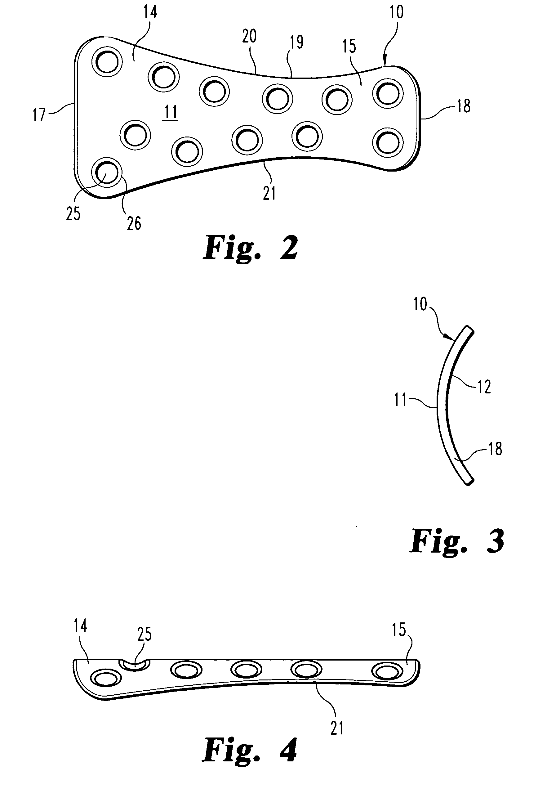
[0008] To address the need for a fixation device for use in reducing the metatarsus, the present invention provides a fixation plate that is sized and configured to generally conform to the shaft of the metatarsus between the head and base. The plate includes a head end that is wider than the base end, with curved side edges that gradually taper between the two ends. In one feature of the invention, the side edges are curved to produce a necked-down portion between the two end edges that has a width less than the width of either end. This contour reduces the overall profile of the plate.
[0010] In an important feature of the invention, the plate is provided with a plurality of screw holes staggered across the length and width of the plate. In the preferred embodiment, twelve screw holes are provided so that the surgeon may select a number, combination and location of bone screws to optimally secure the plate to the bone. Moreover, the array of screw holes provided by the plate of the present invention allows the surgeon to position the screws where they are most needed to reduce a fracture or wedge osteotomy.
[0012] One benefit of the fixation plate of the present invention is that it provides the surgeon with great flexibility in screw placement to reduce a fracture and maintain this reduction until union occurs. Another benefit is that the plate has a minimal prominence or profile above the bone, which reduces soft tissue trauma and minimizes the ability to visibly detect the presence of the plate in the patient's toe. These and other benefits and objects of the invention may be discerned from the following written description taken together with the accompanying figures.

Problems solved by technology

This contour reduces the overall profile of the plate.

Method used


Image

  • Metatarsal fixation plate
  • Metatarsal fixation plate
  • Metatarsal fixation plate

Examples


Embodiment Construction

[0017] For the purposes of promoting an understanding of the principles of the invention, reference will now be made to the embodiments illustrated in the drawings and described in the following written specification. It is understood that no limitation to the scope of the invention is thereby intended. It is further understood that the present invention includes any alterations and modifications to the illustrated embodiments and includes further applications of the principles of the invention as would normally occur to one skilled in the art to which this invention pertains.

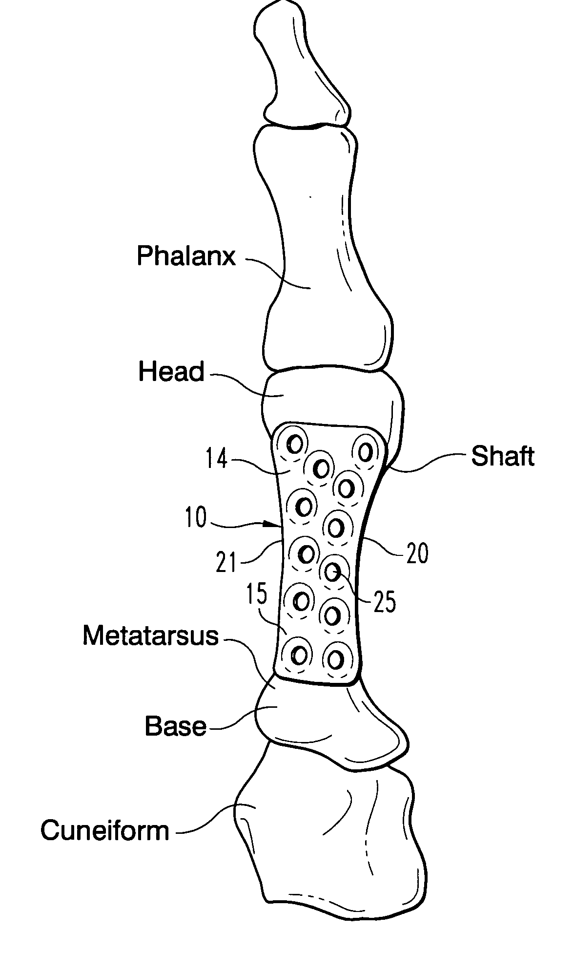
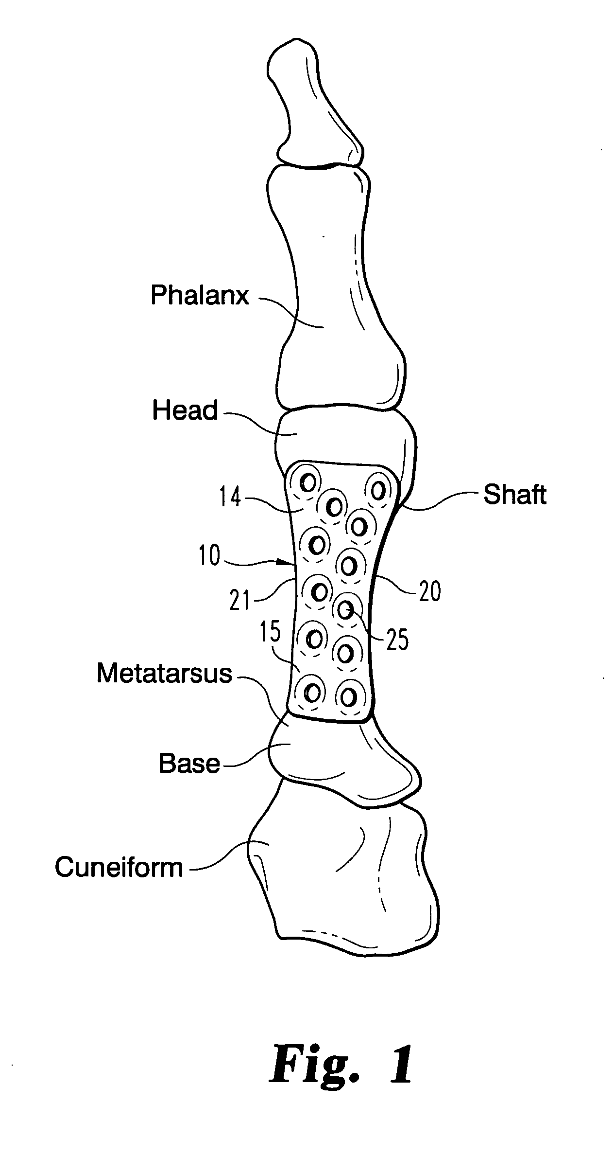
[0018] The first ray of the foot is depicted in FIG. 1 with a plate 10 mounted thereon in accordance with one embodiment of the invention. The first ray includes the cuneiform, the metatarsus and the phalanges. The plate 10 is configured for reducing fractures or bone segments of the shaft metatarsus, preferably between the base and the head of that bone.

[0019] Referring to FIGS. 2-4, more specific details of...


PUM


Abstract

A fixation device for reduction of bone segments of the metatarsus comprises a fixation plate that is sized and configured to generally conform to the shaft of the metatarsus between the head and base. The plate includes a head end that is wider than the base end, with curved side edges that gradually taper between the two ends and produce a necked-down portion between the two ends that narrower than either end. The profile of the plate is further reduced by curving the plate across its width and along the entire length of the plate and by forming the plate at a minimal thickness of about 0.9 mm. The plate is provided with a plurality of screw holes staggered across the length and width of the plate. In the preferred embodiment, two screw holes are provided at each end and a group of four screws are provided adjacent each of the side edges. The screws holes are staggered to avoid conflict of the screws within the bone regardless of how many screws are used to secure the plate to the bone.

Description

BACKGROUND OF THE INVENTION [0001] The present invention relates to a plate for use in fixation of the metatarsal bones of the foot for fracture reduction, hallux valgus correction and similar surgical procedures. [0002] A hallux valgus deformity is a very common foot disorder, often referred to as a bunion. The most common cause attributed to this deformity is improper or ill-fitting footwear, although other biomechanical, traumatic and metabolic factors may actually be more likely etiologies for this condition. The hallux valgus deformity manifests itself as a medial deviation of the first metatarsal, and a lateral deviation and / or rotation of the hallux. This condition can lead to painful motion of the joint, difficulty in wearing shoes, and adjustments in gait that may ultimately cause problems farther up the leg. In minor cases, orthotics may alleviate, but not correct, the deformity. [0003] The goals of surgical approaches to the treatment of a hallux valgus deformity are to r...

Claims


Application Information

Patent Timeline
IPC IPC(8): A61F2/30
CPCA61B17/8085A61B17/8061
Inventor MYERSON, MARKPRASAD, PRIYASANDERS, ROYBREMER, CHRIS
Owner DEPUY PROD INC
Learn More