Bone fixation device for surgical operation, cutting device and band head for the same

Inactive Publication Date: 2006-10-26
PADL
7 Cites 179 Cited by

AI-Extracted Technical Summary

Problems solved by technology

However, when using the above-described bone fixation band, it is necessary to push down the wings 25 on both sides with a pair of pliers or the like after folding back the band 21, hence making it a complicated and delicate...

Method used

[0044] The method of using the bone fixation device 1 constituted in the manner as described above will be described in the followings. FIG. 6 is an illustration showing an example of the area to be applied the bone fixation device 1 according to the present invention. The bone fixation device 1 of the present invention is used for fixing the separated sternal bones by bringing them together when, as shown in FIG. 6 for example, the sternum is completely separated vertically in a operation for the inside of the sternum. That is, the vertically separated sternal bones are unified again, and a plurality of bone fixation devices 1 is wrapped around the bones to fix. Furthermore, in the episternum on the upper part of the sternum, it is fixed with the band 11 passed through by being penetrated with the needle 12. In this case, the tip of the needle 12 is sharply pointed and has the same or slightly wider width of the band 11, so that it enables to suppress damages on the capillary inside the bones compared to the case where the band 11 is inserted by opening a hole in the bone through a spindle or the like. Since the band 11 extends in the direction of inserting the needle 12, it is necessary to pay an attention to the inserting direction of the needle 12 while in operation.
[0048] Next, as shown in FIG. 8(e), the band 11 is folded back to the opposite side and the tip of the band 11 is inserted into the through-hole 15a as shown in FIG. 8(f). Furthermore, as shown in FIG. 8(g), the extra portion is cut off by the cutting device 50 and the tip of the band 11 is further folded back to the front. The band 11 is made of a metallic material and, by folding it back, it is more securely fixed and not to be come off from the through-hole later on. At last, the tip portion of the band head 13 is pressed by the supporting device 40 and the like to be flattened. The necessary areas are fastened by the bone fixation device 1 in the manner as described above and, thereafter, the tissues around the bone are sutured up according to an ordinary procedure to complete the operation.
[0049] By using the bone fixation device 1 as described above, the bones can be securely fixed. Furthermore, the three through-holes 15a-15c have circular shapes, so that each of the holes 15 has two contact points with the strip-shaped band 11 which pass through them. Accordingly, combined with the elasticity and the flexibility of the metal band, the two contact points acts for tight fixation of the band. Furthermore, the band head 13 is constituted of a thin plate and the overall height is kept low even in the fixed state. Thus, patients feel no post-operative pain caused by the contact of...

Benefits of technology

[0015] In this band head, it is effective that the plate is curved or bent so that the band can be easily inserted into the through-holes successively and at least one or more of the through-hole of the band head is in a circular shape or an oval shape.
[0016] For using the bone fixation device of the present invention, the band is set around the bone to be the fixation target, the tip of the band is inserted into the through-holes provided in the band head just like sawing, is folded back after being fully pulled, and is inserted into the through-hole again as necessary for completing the fixation. Since the band head is constituted of a single plate, the thickness of the fixed part can be remarkably thinned compared to the conventional case. Thus, it enables to prevent patients from experiencing an uncomfortable feeling or a pain caused by a contact with tissues after the operation. Furthermore, unlike the conventional device, the band head is not in an angular cylindrical shape, so that the possibility of infections caused by body fluids or tissues caught in the space can be dramatically reduced. Moreover, unlike the conventional device, it is not necessary to push down the wings with a pair of pliers, so that it can be easily treated. Moreover, the device can be manufactured ...

Abstract

Provided is a bone fixation band which can be easily handled, enables to securely fasten the bone, and also to prevent the post-operative inconveniences by forming the head part as thin as possible. The band head of the bone fixation device is constituted of a plate being bent in roughly an N-letter shape. The plate comprises three through-holes arranged in the extended direction of the band. The band is passed through into the through-hole just like sawing and then is folded back to pass through again into the through-hole and fixed. A sharp and curved needle is provided at the tip of the band for easily being set around the bone to be a fixation target and also for making a hole in the bone so that the band can be easily passed through.

Application Domain

Technology Topic

Bones fixationHead parts +3

Image

  • Bone fixation device for surgical operation, cutting device and band head for the same
  • Bone fixation device for surgical operation, cutting device and band head for the same
  • Bone fixation device for surgical operation, cutting device and band head for the same

Examples

  • Experimental program(4)

Example

First Embodiment
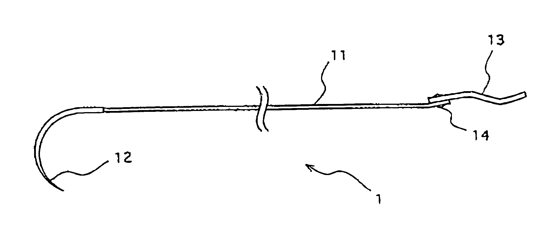
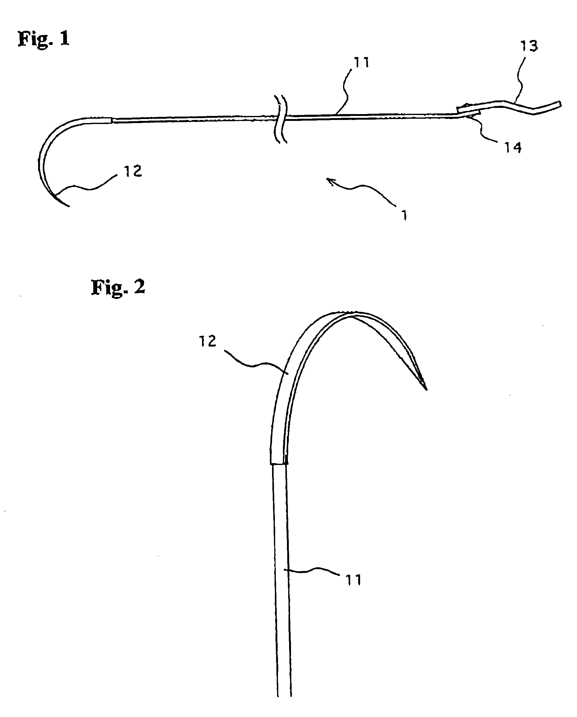
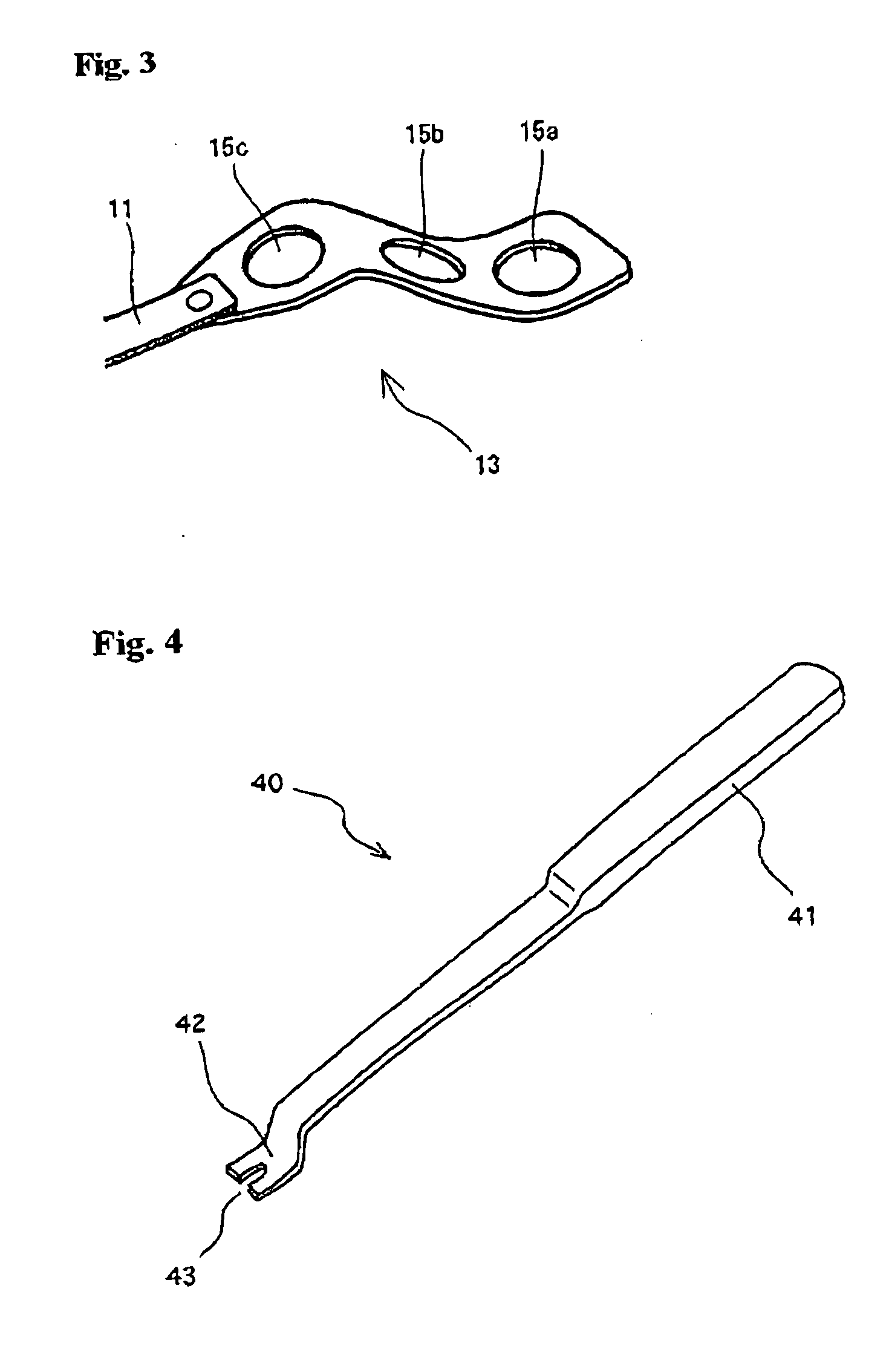
[0038]FIG. 1 is an illustration showing the configuration of the first embodiment of the fixation device according to the present invention. As shown in FIG. 1, a bone fixation device 1 comprises a long strip-shaped band 11, a needle 12 provided at one end of the band 11, and a band head 13 provided at the other end of the band 11. Each of the elements is made of biocompatible metallic material and, desirably, of the non-ferritic (non-magnetic) high quality stainless steel. As an example of such metal, stainless steel 316LVM (product name), a product of Sandvik AB, can be preferably used.
[0039] The band 11 has flexibility and plasticity and it is formed to have a length of about 150-400 mm, a width of about 1.5-12.0 mm, and a thickness of about 0.1-1.0 mm, for example. The needle 12 is curved so that it can be set behind the bone and then pulled through to the front again. It is formed in a length of about 40-60 mm, a width of about 1.5-3.5 mm, and a thickness of about 1.0-2.0 mm. FIG. 2 shows a needle 12 of the embodiment. As shown in the drawing, the needle 12 is entirely flat, has a sharply pointed tip, and at least a part of it is of the same width as that of the band 11 or slightly wider. With this configuration, the band 11 can be passed through by inserting the needle 12 into a part of the episternum or the like, for example. As for the needles 12, the dimensional shape, the degree of the curvature and the like are to be determined appropriately in accordance with the area to be applied. For example, a round needle called “round point” may be used in an area which is soft and easy to insert the needle, and a tapered cutting needle with a triangular pyramid point in the embodiment is used for an area where it is hard to insert the needle.
[0040] The band 11 is fixed to the band head 13 through a caulking pin or rivets 14 and, as shown in FIG. 1, is slightly curved or bent in an N-letter shape. The head 13 is formed in a size of about 7-50 mm in length, 4-15 mm in width, and 0.2-2.0 mm in thickness before being bent. FIG. 3 is a perspective view showing the configuration of the head 13. As shown in the drawing, the head 13 has a shape of rectangular plate with round edges whose one end is narrowed to the width of the band 11. The head 13 is provided with three through-holes 15a, 15b, and 15c arranged at almost equal intervals in the extended direction of the band 11. Furthermore, the band head 13 is curved or bent at an obtuse angle between with the adjacent through-holes 15 and, as a whole, it forms roughly an N-letter shape. The through-holes 15 are circles with the diameter which is the same as the width of the band 11 or slightly larger (for example, about 1.5-12 mm), and the distance from the center of one through-hole to the center of the next through-hole is the radius of the hole or shorter (for example, about 2-15 mm). The N-letter shape of the band head makes easier for the band 11 to pass through as described above, and can prevent the band 11 from passing the through-holes 15 in the wrong order.
[0041] A device used for using the bone fixation device 1 will be described by referring to FIG. 4 and FIG. 5. FIG. 4 shows a supporting device 40 and FIG. 5 shows a cutting tool 50. The supporting device 40 is a device for pushing down the band head 13 when the band 11 taken out from the through-holes 15 is pulled. It comprises a grip 41 and a supporting end 42 being bent in a crank shape. A U-shape groove 43 in a width slightly wider than the band 11 is provided on the tip of the supporting end 42. Through pushing down the band head 13 with applying the band to the U-shape groove 43 makes it possible to pull the band 11 without loosening the band head 13 from the bone.
[0042]FIG. 5(a) is a perspective view showing the overall configuration of the cutting tool 50, and FIG. 5(b) is an enlarged view of the tip of the tool. As shown in the drawings, the cutting tool 50 has the configuration of a pair of pliers, and is comprised of a guide groove 51 for guiding the band 11 which is of the same width as that of the band 11 or slightly wider, a blade 52 for cutting the band, and a handle 53 for handling the blade. The guide groove 51 is in communication with the handle 53, and the band 11 can be inserted into the guide groove 51 to be pulled out at some length toward the handle 53. As shown in FIG. 4(b), the blade 52 has a curved shape, so that it can cut the band 11 in a round cut face.
[0043] The dimensions and the shapes of the above-described structural elements can be appropriately altered according to the condition of embodiment such as the area of to be applied the bone fixation device 1.
[0044] The method of using the bone fixation device 1 constituted in the manner as described above will be described in the followings. FIG. 6 is an illustration showing an example of the area to be applied the bone fixation device 1 according to the present invention. The bone fixation device 1 of the present invention is used for fixing the separated sternal bones by bringing them together when, as shown in FIG. 6 for example, the sternum is completely separated vertically in a operation for the inside of the sternum. That is, the vertically separated sternal bones are unified again, and a plurality of bone fixation devices 1 is wrapped around the bones to fix. Furthermore, in the episternum on the upper part of the sternum, it is fixed with the band 11 passed through by being penetrated with the needle 12. In this case, the tip of the needle 12 is sharply pointed and has the same or slightly wider width of the band 11, so that it enables to suppress damages on the capillary inside the bones compared to the case where the band 11 is inserted by opening a hole in the bone through a spindle or the like. Since the band 11 extends in the direction of inserting the needle 12, it is necessary to pay an attention to the inserting direction of the needle 12 while in operation.
[0045]FIG. 7 and FIG. 8 are illustrations showing an example of the method for using the bone fixation device 1. In surgery, at first, the needle 12 is set around the bone to be the target of the fixation, or, for the episternum, the needle 12 is inserted into the episternum to pass the band 11 through. At this time, it is necessary to pay attention to the direction of the band so that the surface side (the top side in FIG. 1) of the band head 13 comes face up. Furthermore, it is necessary to mind that the band 11 is not twisted while handling the needle.
[0046] After setting the band 11 around the bone, the needle 12 is cut off (not shown) from the band 11 using the cutting tool 50 or other devices. After confirming that there is no twist in the band 11, the free end of the band 11 is pulled out from the backside of the first through-hole 15a. Then, it is inserted into the second through-hole 15b, and pulled out again from the third through-hole 15c, as shown in FIGS. 7(a) and 7(b). In this case, since the band head 13 is roughly in an N-letter shape, the direct insertion of the tip of the band 11 in the through-holes makes it possible to pass through the three adjacent through-holes 15a-15c. In addition, the band 11 can be inserted to the surface side or backside in the right order.
[0047] Next, as shown in FIG. 7(c), protrusion part A between the second through-hole 15b, and the third through-hole 15c is flattened by using forceps 30 such as the needle holding device. Accordingly, the part of the band head 13 which contacts with the bone becomes flattened, so that the pressure applied by the head 13 is dispersed, and the inflammation caused by the invasion of tissues or body fluid into space between the bone and the band head 13 can be prevented. Next, as shown in FIG. 7(d), the band 11 is fully pulled with the needle holding device 30 while pressing the bottom part of the band head 13 with the supporting device 40 for ensuring that the bones are closely contacted with each other by the fixation device 1.
[0048] Next, as shown in FIG. 8(e), the band 11 is folded back to the opposite side and the tip of the band 11 is inserted into the through-hole 15a as shown in FIG. 8(f). Furthermore, as shown in FIG. 8(g), the extra portion is cut off by the cutting device 50 and the tip of the band 11 is further folded back to the front. The band 11 is made of a metallic material and, by folding it back, it is more securely fixed and not to be come off from the through-hole later on. At last, the tip portion of the band head 13 is pressed by the supporting device 40 and the like to be flattened. The necessary areas are fastened by the bone fixation device 1 in the manner as described above and, thereafter, the tissues around the bone are sutured up according to an ordinary procedure to complete the operation.
[0049] By using the bone fixation device 1 as described above, the bones can be securely fixed. Furthermore, the three through-holes 15a-15c have circular shapes, so that each of the holes 15 has two contact points with the strip-shaped band 11 which pass through them. Accordingly, combined with the elasticity and the flexibility of the metal band, the two contact points acts for tight fixation of the band. Furthermore, the band head 13 is constituted of a thin plate and the overall height is kept low even in the fixed state. Thus, patients feel no post-operative pain caused by the contact of the band head 13 with their tissues. Moreover, little space is generated between the band 11 and the band head 13 in the fixed state, so that no inflammation is caused by the tissues invaded inside the device. In addition, the cutting tool 50 cuts the part of the band 11 in a semicircle shape, so that no tissues are damaged from the cut part.

Example

Second Embodiment
[0050] Next, the second embodiment of the bone fixation device according to the present invention will be described. FIG. 9 and FIG. 10 are illustrations for describing a bone fixation device 60 according to the embodiment and the using method of the device. In the embodiment, a band head 61 of the band 60 is not in roughly an N-letter shape and is constituted of a single flat plate comprising three through-holes 62a, 62b, and 62c. Other configurations are the same as those of the first embodiment shown in FIG. 1.
[0051] The band 63 is placed around the bone by using the bone fixation device 60 of the embodiment, and the needle is cut off from the band 63 by using a device such as a cutter or the cutting tool 50 (not shown). After confirming that there is no twist in the band 63, as shown in FIGS. 9(a)-9(b), the free end of the band is inserted into the first through-hole 62a from over the bead 61 and is pulled out to the top from the third trough-hole 62c. Then, as shown in FIG. 9(c), the band 63 is turned over to be inserted into the second through-hole 62b, and is pulled out to the surface again from the first through-hole 62a.
[0052] Next, as shown in FIG. 10(d), the band is pulled by the needle holding device 30 while pressing the bottom of the band in the third through-hole 62c by the supporting device 40. Furthermore, as shown in FIG. 10(e), the end of the band is pulled by the needle holding device 30 by pressing the bottom of the band in the first through-hole 62a by the supporting device 40. After confirming that the bone is fixed in this manner under a desirable state, as shown in FIGS. 10(f), the extra portion of the band 63 coming out from the first through-hole 62a is cut off thereby completing the fixation. After that, the tissues around the bone are sutured up through an ordinary procedure thereby completing the operation. The cutting of the band 63 may be performed by the cutting device 50 shown in FIG. 5.
[0053] In the embodiment, the metallic band 63 is folded back after pulling out from the third through-hole 62c, and the part of the band which is then inserted into the first through-hole 62a from the second through-hole 62b is constantly pushed down. Thus, the band 63 is not to be come off from the through-holes after the fixation. Thus, different variations on the insertion manner of the band into the through-holes may be devised.

Example

Third Embodiment
[0054]FIG. 11 is a side view showing the configuration of the third embodiment of the bone fixation device according to the present invention. As shown in FIG. 11, in a bone fixation device 70 of the present invention, a band 71 and a band head 72 are integrally molded. In this bone fixation device 70, the head 72 is formed to be thicker than the band 71 for increasing the strength. Other configurations are the same as those of the bone fixation device 60 of the second embodiment. With this configuration, it becomes unnecessary to fasten the band and the band head by the rivet. Thus, the number of components can be decreased and the height of the bone fixation device 70 can be lowered for the height of the rivet. As the method for manufacturing the bone fixation device 70, there may be a method in which a metal plate with the thickness of the band head 72 is prepared and is cut into a desired shape, and only the part for the band 71 is then stretched thin.

PUM

no PUM

Description & Claims & Application Information

We can also present the details of the Description, Claims and Application information to help users get a comprehensive understanding of the technical details of the patent, such as background art, summary of invention, brief description of drawings, description of embodiments, and other original content. On the other hand, users can also determine the specific scope of protection of the technology through the list of claims; as well as understand the changes in the life cycle of the technology with the presentation of the patent timeline. Login to view more.

Similar technology patents

Plastic bag and method

InactiveUS7112169B2Prevent snagEasily insertEnvelopes/bags making machineryPaper/cardboard wound articlesAntistatic MaterialsPlastic bag
Owner:HONSTRATER RICHARD A

Software control flow watermarking

InactiveUS20050055312A1Easily insertDifficult for attackerProgram/content distribution protectionSecuring communicationSoftwareControl flow
Owner:RIVERSIDE RES INST

Disposable animal waste cleaning device and method of making

InactiveUS20050006914A1Easily insertImprove and simplifyRoad cleaningOther apparatusAnimal waste
Owner:BRITISH AMERICAN IND +1

Classification and recommendation of technical efficacy words

  • Easily insert
  • Thin thickness

Osteoimplant and method of making same

InactiveUS20060030948A1Easily insertGood bone contactBone implantJoint implantsBone particleBiomedical engineering
Owner:WARSAW ORTHOPEDIC INC

Intervertebral implant

InactiveUS20050085917A1Reduce overall structural heightEasily insertSurgeryJoint implantsVertebraBiomedical engineering
Owner:CENTINEL SPINE LLC

Tape drive and printing apparatus

InactiveUS7150572B2Easily insertPrinting mechanismsInk ribbonsPush pullStepper
Owner:VIDEOJET TECH INC

Tree pole coupler system

Owner:THE PRE LIT TREE CONCEPT

Apparatus for transcutaneous electrical stimulation of the tibial nerve

InactiveUS20140228927A1Low profileThin thicknessElectrotherapyArtificial respirationElectro acupuncturePosterior tibial nerve
Owner:RELIEF BAND MEDICAL TECH
Why Eureka
Try Eureka