It is known that bending and straightening the coiled tubing in wellsite operations and
spooling the coiled tubing on a reel causes
low cycle fatigue in the coiled tubing, which if left unchecked can lead to failure of the coiled tubing.
There are occasions however when connections are required between coiled tubing strings, for example, in situations when the length of coiled tubing required for an operation exceeds the capacity of the coiled tubing reel; when the capacity of handling equipment limits the permissible weight of the coiled tubing reel, thereby limiting the length of coiled tubing permitted to be spooled thereon; when a repair is required in coiled tubing; or when retrieving a length of coiled tubing from a well.
Welding in
field conditions is more challenging and less robust than the bias-type
welding that is used under controlled conditions in coiled tubing manufacturing.
As failure of coiled tubing welds can lead to unsafe working conditions,
verification testing using methods such as X-
ray,
tensile testing, or pressure testing of the butt weld performance is required prior to deployment of the welded coiled tubing in a wellbore.
In addition, often connections are required in areas where explosive conditions may be present which lead to the need to take additional safety precautions in field
welding.
In sum, field
welding is a time-consuming and operationally undesirable method for connecting two segments of coiled tubing together.
Stiff connectors however are not spooled with the coiled tubing on the coiled tubing reel as they lack the requisite flexibility to bend around the coiled tubing reel and deployment equipment.
As a result, stiff connectors present a number of drawbacks.
As such, they cause operational difficulties because they do not pass through the
wellhead equipment.
Although operational difficulties are reduced by the use of internal connectors, the use of stiff internal connectors in coiled tubing nevertheless poses difficulties.
As the coiled tubing is bent in routine activities, the end of the coiled tubing adjacent to the end of the stiff connector flexes to an undesirable degree.
Such straining of the coiled tubing at a stiff connection can quickly make the coiled tubing unsuitable or unsafe for use.
It is common that tubing used with a connector becomes unsuitable for use or fails after only a few bending / straightening cycles.
In general, stiff connectors lack the flexibility to permit them to be spooled onto the coiled tubing reel.
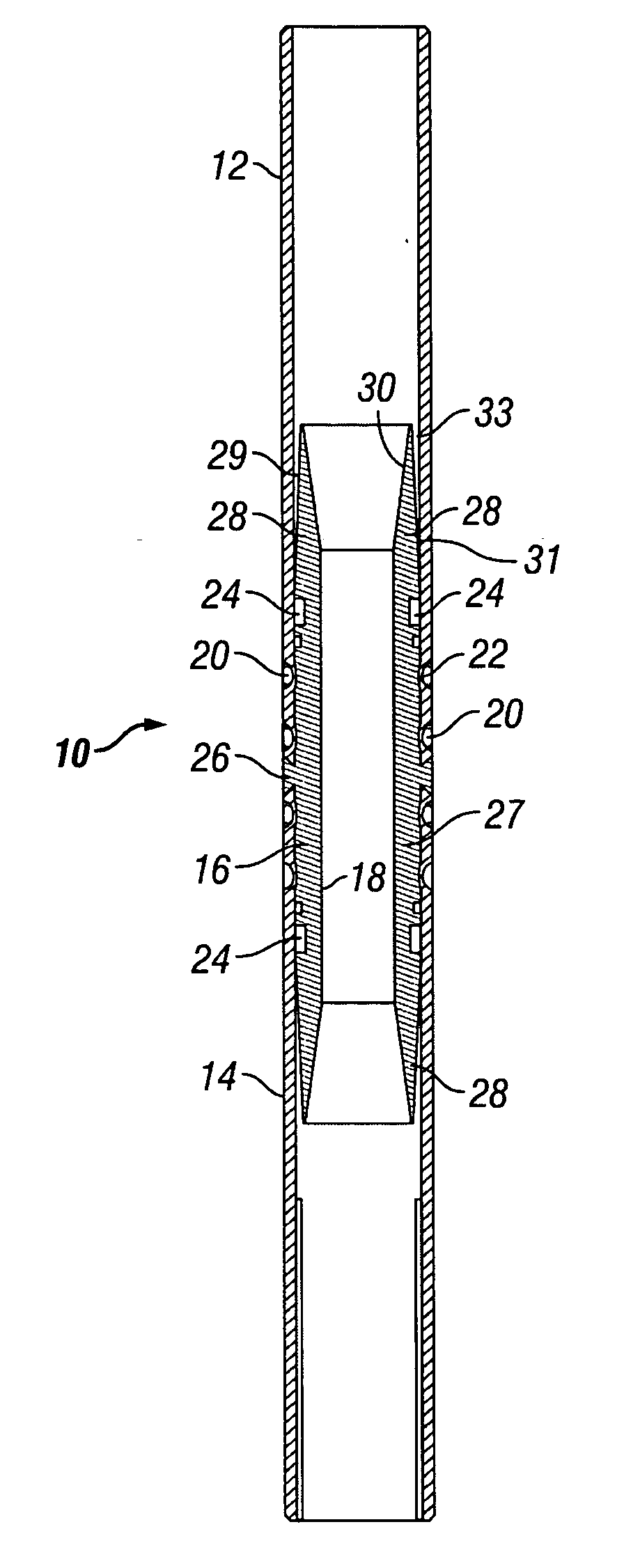
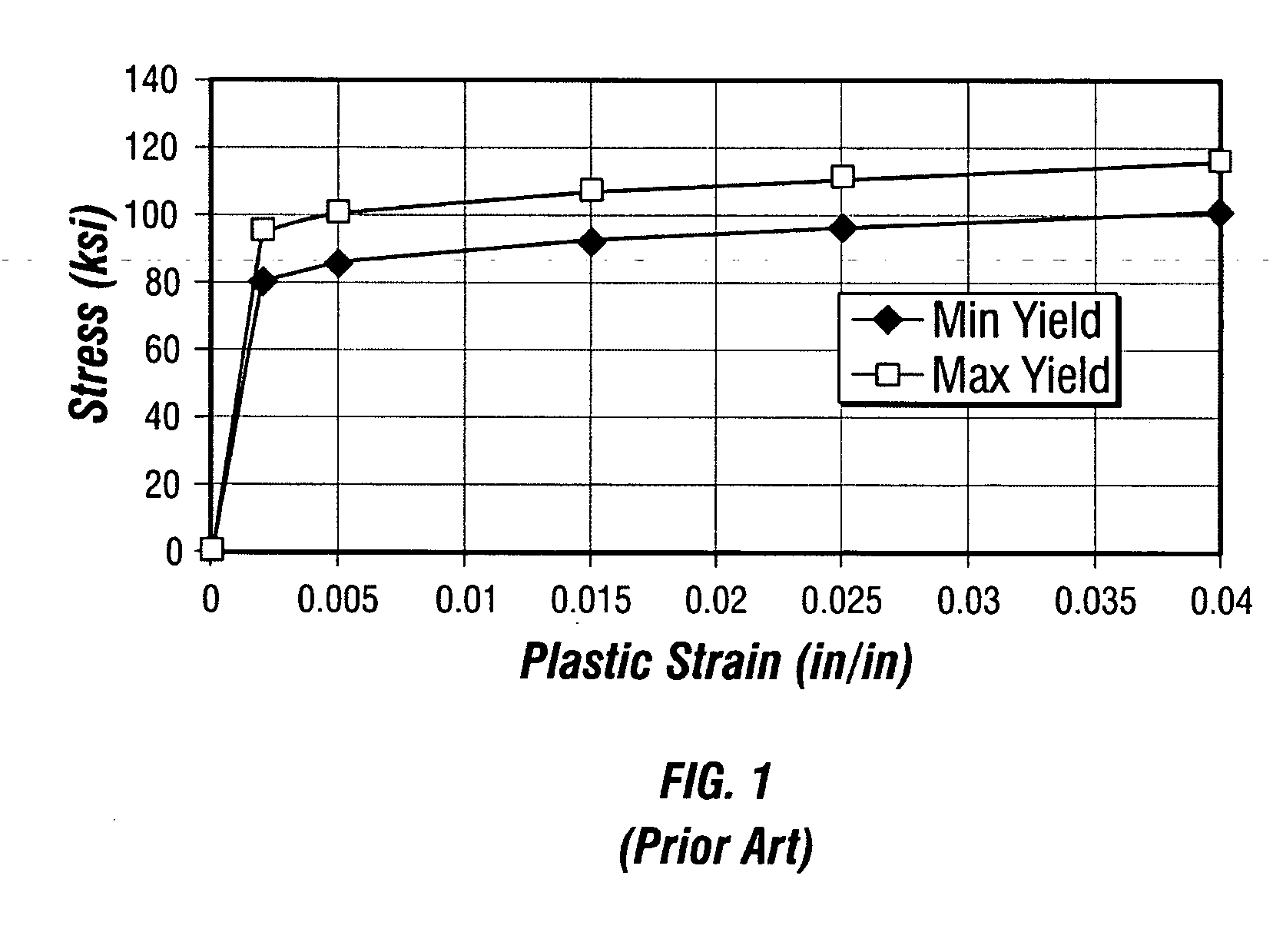
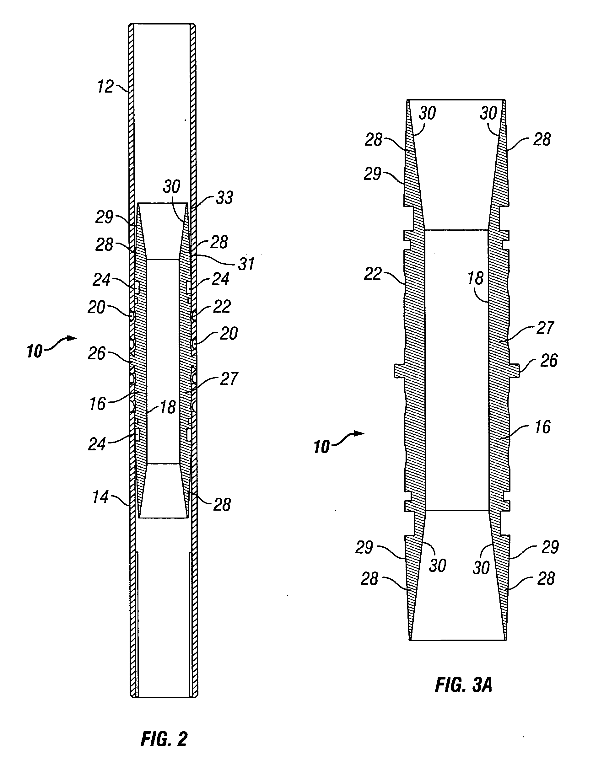
A particular challenge to using a flexible connector and coiled tubing made of conventional materials is the varying range of material properties generally accepted in materials such as commercial grade steel used to make coiled tubing.
This variation in yield strength is the foundation for design limitations between the connector and the coiled tubing.
For example, if one of the components has a yield strength near the minimum allowed (“low yield component”) and the other component has a yield strength near the maximum allowed (“high yield component”), the strain in the components under the same conditions would differ, leading to differing
low cycle fatigue lives.
In such situations, when the low yield component reaches the yield point, the low yield component begins to deform plastically but the high yield component remains in its elastic range and does not yield.
Since
low cycle fatigue life is closely related to the amount of cyclic strain, the low yield component will fail significantly sooner than the high yield component.
This is not easily achieved given the variation of material properties and the varying stress / strain conditions along the bend distance between the flexible section of the connector and the length of the coiled tubing string beyond the influence of the connector end section.
It has been observed that coiled tubing connectors that use a flexible section between two stiff end connections often have inconsistent performance and periodically fail much sooner than expected.

