Elevator door apparatus

a technology for elevators and doors, applied in the direction of building lifts, transportation and packaging, etc., can solve the problems of large difference in atmospheric pressure between elevator shafts and halls, increased frictional resistance of guide devices or atmospheric, and constricted air flow, so as to enhance the force of a door closer

Inactive Publication Date: 2006-11-02
TOSHIBA ELEVATOR KK
View PDF8 Cites 23 Cited by
  • Summary
  • Abstract
  • Description
  • Claims
  • Application Information

AI Technical Summary

Benefits of technology

[0020] An elevator door apparatus according to the present invention reliably closes a hall door by transmitting the driving force of a car door to the hall door until the hall door is completely closed and without the need to enhance the force of a door closer or to complicate an engaging device for the hall door and car door. It is another object of the present invention to provide an elevator door apparatus that can operate normally even if a high wind pressure acts on the hall door.
[0023] Further, the elevator door apparatus preferably comprises regulating means or attenuation applying means. If the car door has been closed to release the engaging device, the regulating means inhibits the movable vane from moving toward a side on which the engagement occurs. The attenuation applying means reduces the speed at which the movable vane is moved by the spring mechanism in a direction in which the movable vane approaches or leaves the fixed vane.
[0025] With the elevator door apparatus according to the present invention, the driving force of the car door is transmitted to the hall door until the hall door is completely closed. Then, the hall door can be reliably closed by appropriately maintaining an automatic closing force until the hall door is completely closed and without the need to enhance the force of the door closer or to complicate the engaging device for the hall door and car door. Therefore, the hall door can be normally opened and closed even when a high wind pressure acts on the hall door.

Problems solved by technology

Thus, a large difference in atmospheric pressure occurs between the elevator shaft and the hall.
However, as the door is closed, the flow of air is constricted.
As a result, there may occur an increase in the frictional resistance of the guide device or in the atmospheric pressure acting on a door stop surface.
As a result, the tendency to suffer the above disadvantage has become more significant.
This affects a space in which the elevator is installed.
Since a high-rise building comprises a plurality of elevators, it is economically disadvantageous to take the above measure for each of a large number of hall doors installed on each floor.
Further, the latter of the previously described door apparatuses has a very complicated mechanism and is thus difficult to regulate.
Accordingly, this apparatus is also economically disadvantageous.
Disadvantageously, this further complicates the mechanism of the apparatus.

Method used


Image

  • Elevator door apparatus
  • Elevator door apparatus
  • Elevator door apparatus

Examples


first embodiment

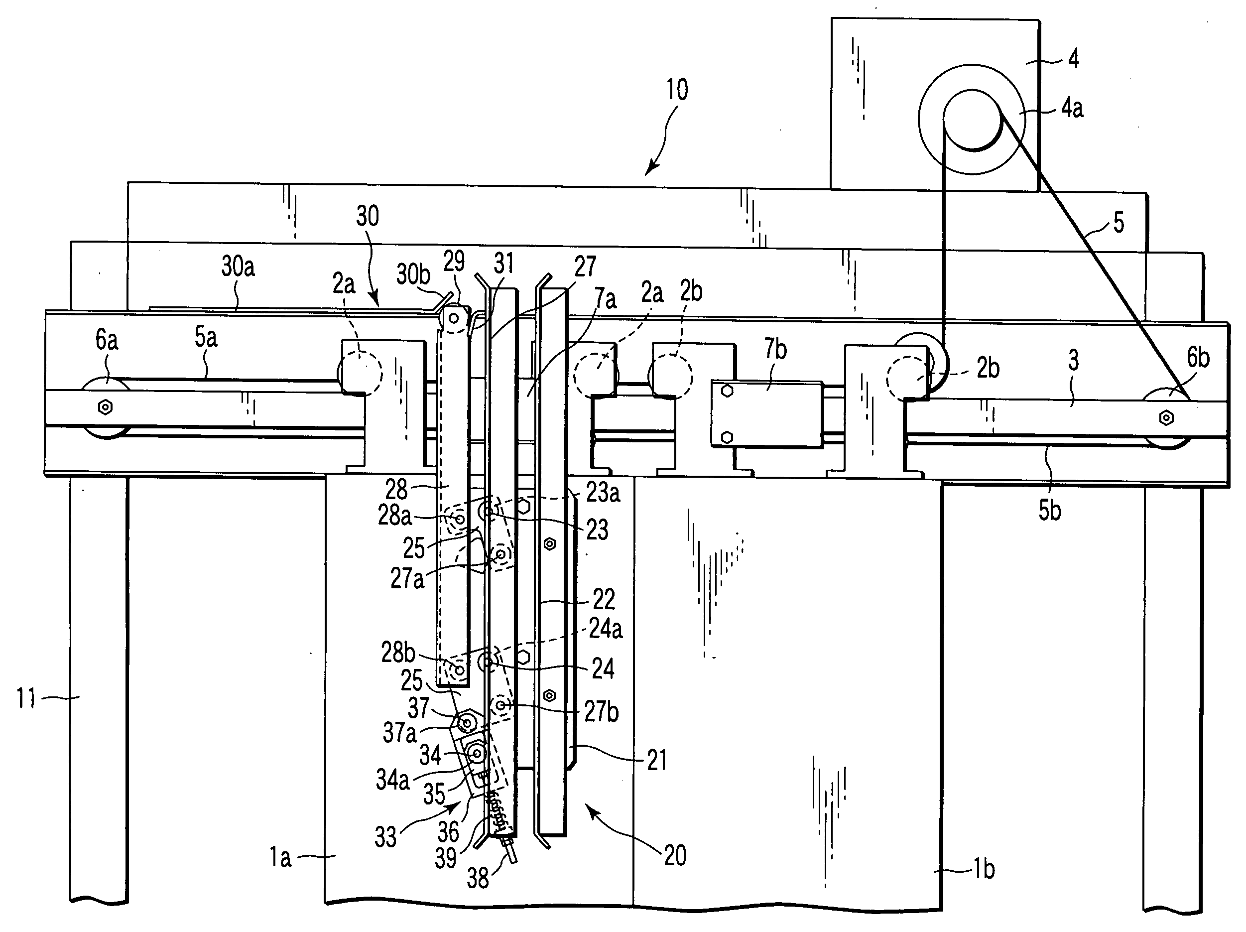
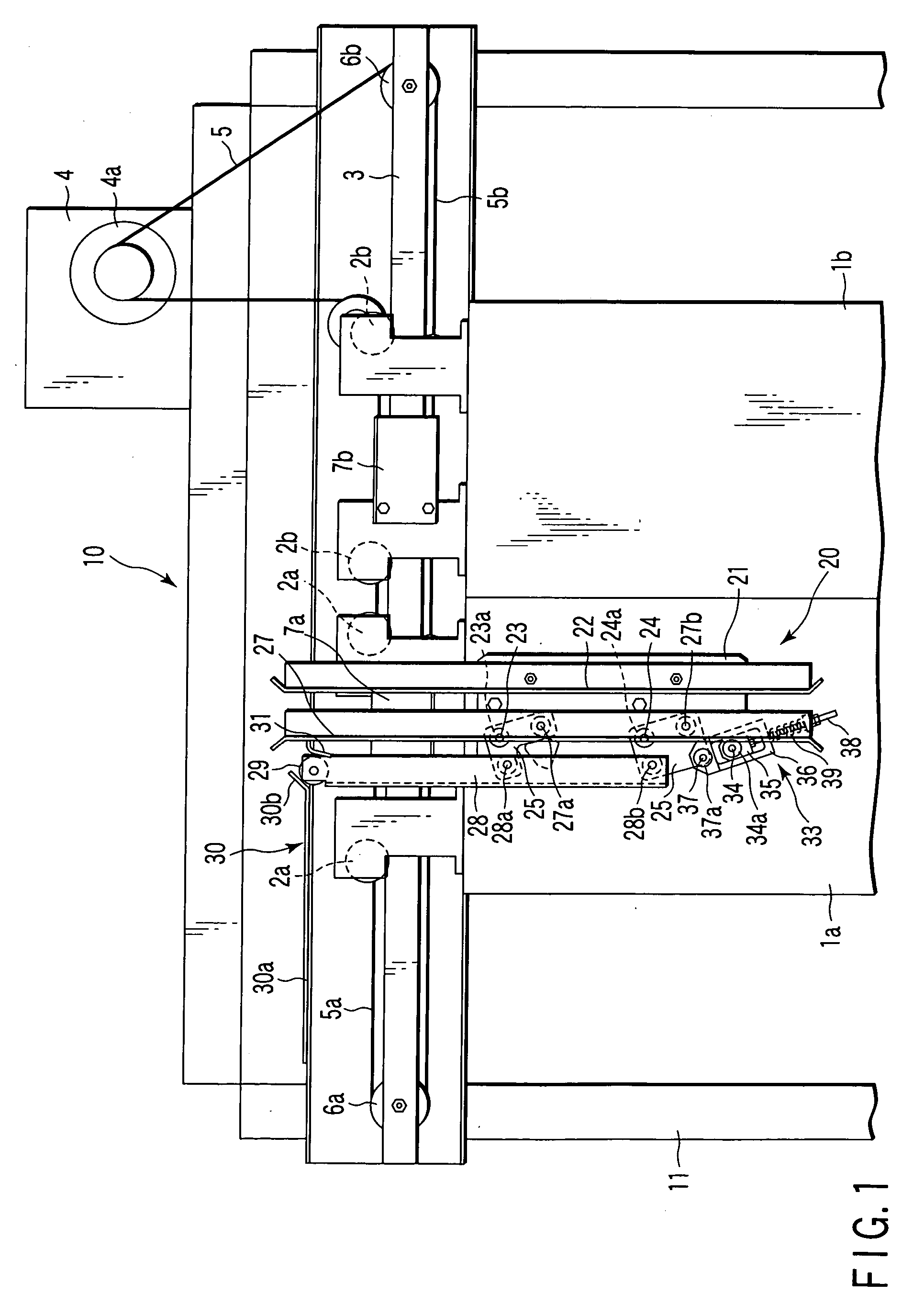
[0056] An elevator door apparatus 10 according to a first embodiment will be described with reference to FIGS. 1 to 11. The elevator door apparatus 10 comprises car doors 1a and 1b, hall doors 100a and 100b, a driving device 4, an engaging device 20, and a lock mechanism 101. FIG. 1 shows the center open type car doors 1a and 1b mounted at an entrance provided in the front of a car, as viewed from a hall. A frame member 11 is installed in the front of the car. A laterally elongated hanger rail 3 is attached to the top of the frame member 11 so as to extend in a horizontal direction. The car doors 1a and 1b have hanger roller 2a and 2b.

[0057] Hanger rollers 2a and 2b are provided on the top of paired car doors 1a and 1b. The car doors 1a and 1b are suspended from hanger rail 3 by using hanger rollers 2a and 2b so as to stand side by side. The car door 1a and 1b move in a lateral direction along the hanger rail 3 to open and close the entrance of the car.

[0058] A driving device 4 fo...

second embodiment

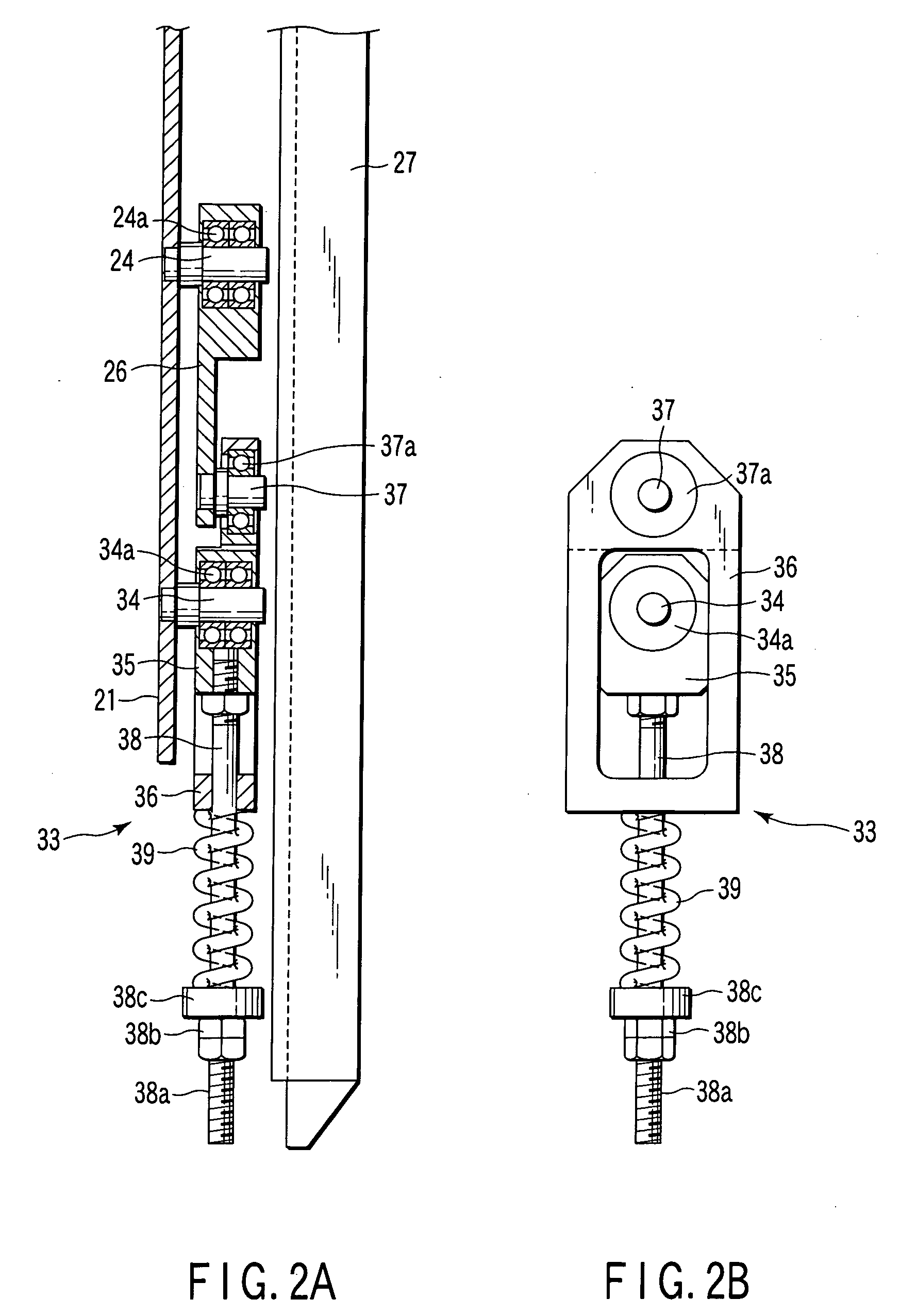
[0102] An elevator door apparatus 10 of a second embodiment according to the present invention will be described with reference to FIGS. 12 and 13. In the elevator door apparatus 10 according to the present embodiment, the configuration of the spring unit 33 is partly different from that in the first embodiment. In FIGS. 12 and 13, the spring unit 33 comprises the block 35, the block frame 36, the spring guide bar 38, the compression spring 39, and a shock absorber 53.

[0103] The base plate 21 is fixed to the car door 1a. The shaft 34 is fixed to the base plate 21. The block 35 is rotatably assembled to the shaft 34 via the bearing 34a. The block frame 36 surrounds the block 35 and can slide with respect to the block 35. The top of the block frame 36 is rotatably attached to the shaft 37 via the bearing 37a. The shaft 37 is fixed to the bottom of the link plate 26.

[0104] The spring guide bar 38 is attached to the bottom of the block 35 and slidably extends downward through the bloc...

third embodiment

[0109] Now, with reference to FIGS. 14 to 16, description will be given of the elevator door apparatus 10 according to a third embodiment. In FIG. 14, the engaging device 20 comprises the base plate 21, the fixed vane 22, link plates 60 and 61, the movable vane 27, a mounting plate 62, a cam mechanism, and the spring unit 33. The base plate 21 is fixed to the car door 1a. The shafts 23 and 24 are fixed to the base plate 21. The link plates 60 and 61 are rotatably assembled to the shafts 23 and 24 via the bearings 23a and 24a, respectively.

[0110] The movable vane 27 has the shafts 27a and 27b. The link plate 60 is connected to the shaft 27a. The link plate 61 is connected to the shaft 27b. The link plates 60 and 61 and the movable vane 27 constitute a sub-parallelogrammic link mechanism. The spring unit 33 is attached to the bottom of the link plate 61 via the shaft 37 as in the case of the first embodiment.

[0111] The mounting plate 62 is fixed to the top of the movable vane 27. A ...


PUM


Abstract

An elevator door apparatus includes an engaging device which engages car doors with hall doors. The engaging device uses a spring unit to urge a movable vane provided in each of the car doors. While the doors are moving, engaging rollers supported by the hall doors are sandwiched between the movable vane and a fixed vane. Thus, the driving forces of the car doors are transmitted to the hall doors. When the hall doors reach a door stop position, the movable vane is moved away from the fixed vane. Thus, the car doors are disengaged from the hall doors. At this time, a direction in which the elastic force of the spring mechanism acts is switched. Consequently, the car doors and the hall doors are stably held so that the car doors remain disengaged from the hall doors.

Description

CROSS REFERENCE TO RELATED APPLICATIONS [0001] This is a Continuation Application of PCT Application No. PCT / JP2005 / 006224, filed Mar. 24, 2005, which was published under PCT Article 21(2) in English. [0002] This application is based upon and claims the benefit of priority from prior Japanese Patent Application No. 2004-092951, filed Mar. 26, 2004, the entire contents of which are incorporated herein by reference.BACKGROUND OF THE INVENTION [0003] 1. Field of the Invention [0004] The present invention relates to an elevator door apparatus comprising an engaging device that engages a car door with a hall door. [0005] 2. Description of the Related Art [0006] An elevator hall in a building is provided with an entrance to a car of an elevator. Hall doors, which are of sliding type, are attached to the entrance. The hall door is normally closed. When the car, moving through an elevator shaft, reaches a floor of the elevator hall, the hall door is opened and closed under the driving force...

Claims


Application Information

Patent Timeline
Patent Type & Authority Applications(United States)
IPC IPC(8): B66B13/12B66B13/20
CPCB66B13/20B66B13/12
Inventor KINOSHITA, TOORUSOMEYA, SEIICHITAKASAWA, SATOSHIMURAKAMI, SHINISHIKAWA, YOSHINOBU
Owner TOSHIBA ELEVATOR KK
Why Eureka
Try Eureka