Mounting bracket structure

a technology of mounting brackets and brackets, which is applied in the direction of machine supports, electrical apparatus casings/cabinets/drawers, coupling device connections, etc., can solve the problems of increasing costs, and achieve the effect of easy positioning of the fastening member and easy breakage of the mounting brack

Inactive Publication Date: 2006-11-02
YAZAKI CORP
View PDF5 Cites 12 Cited by
  • Summary
  • Abstract
  • Description
  • Claims
  • Application Information

AI Technical Summary

Benefits of technology

[0019] In the invention, there is achieved an advantage that there can be provided the mounting bracket structure which is broken when a load is applied in the predetermined direction perpendicular to the axis of the fastening

Problems solved by technology

Therefore, such a structure has the following problems.
Namely, in the case where the rupture load can be applied only in a direction perpendicular to the axial direction of the bolt (here, for example, in a direction from the through hole of the mounting bracket toward an interconnecting portion connected to the electric connection box body), the development and concentration of the above bending stresses will not occur even if the notch portion or the hole portion exists between the through hole and the above interconnection portion of the mounting bracket, and therefore there is a structural problem that the

Method used


Image

  • Mounting bracket structure
  • Mounting bracket structure
  • Mounting bracket structure

Examples


Embodiment Construction

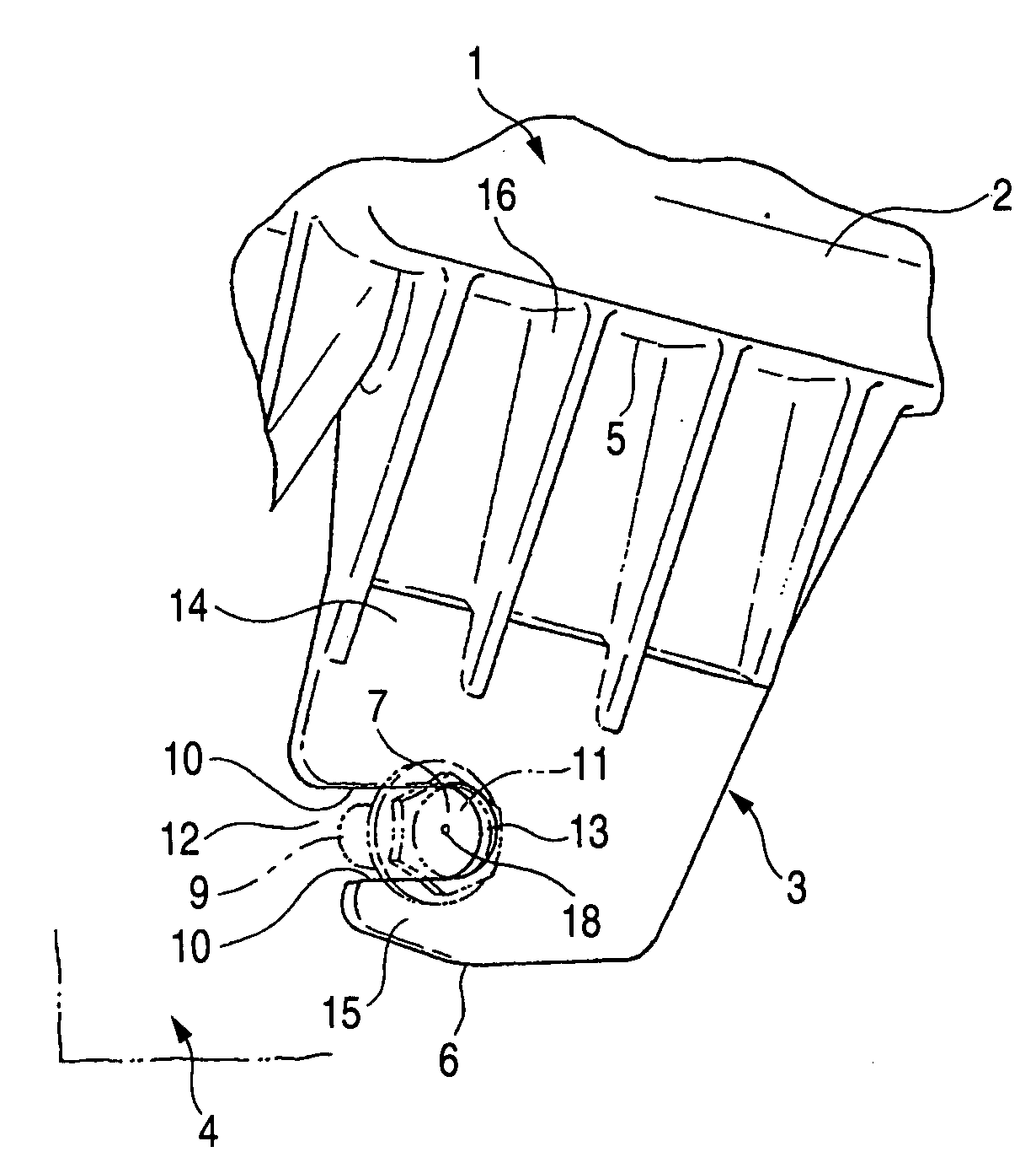
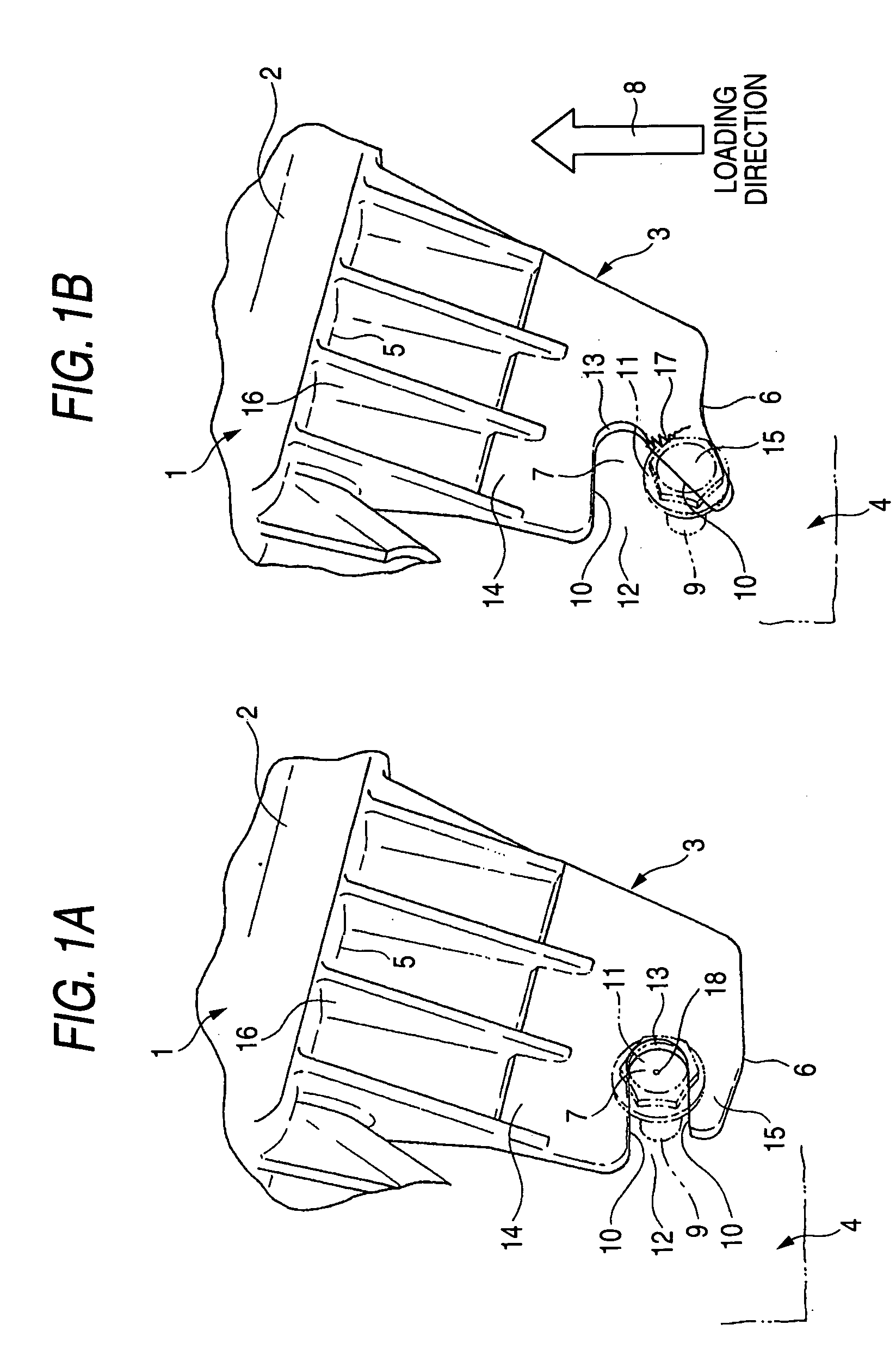
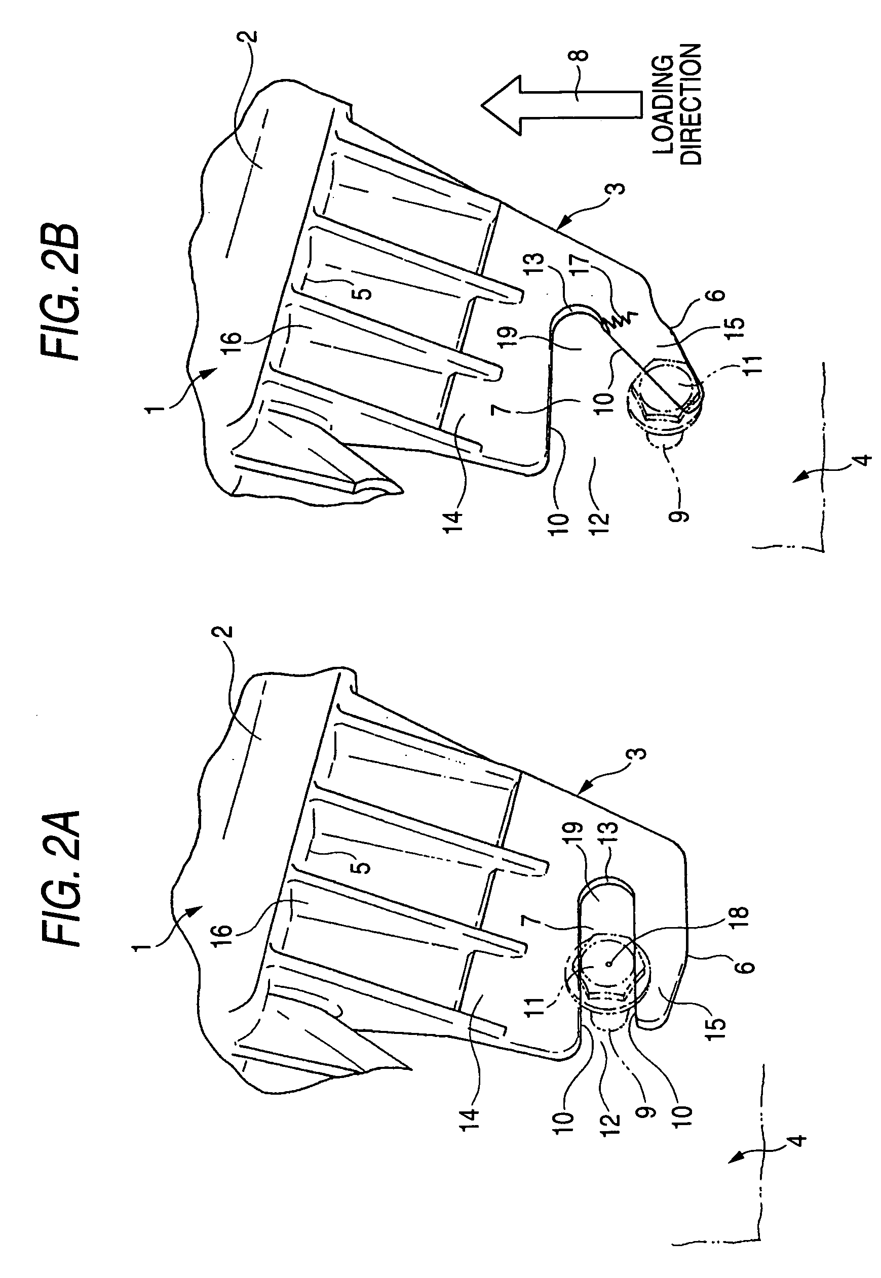
[0023] Description will now be made with reference to the drawings. FIGS. 1A and 1B are views showing one embodiment of a mounting bracket structure of the present invention, and FIG. 1A is a perspective view showing a fixed condition of a mounting bracket, and FIG. 1B is a perspective view showing a broken condition of the mounting bracket.

[0024] In FIGS. 1A and 1B, an electric connection box (corresponding to “an attachment part” recited in the appended claims) for mounting on a vehicle such as an automobile includes an electric connection box body 1. The electric connection box body 1 includes a box member 2, and a plurality of circuit boards (not shown) contained in this box member 2. A housing (not shown) of a connector connecting portion for connection to a wire harness (not shown) is formed integrally with the box member 2. Also, a plurality of mounting brackets 3 (only one of which is shown here) are formed integrally with the box member 2. The electric connection box is ad...


PUM


Abstract

When a predetermined rupture load is applied to a mounting bracket formed on an attachment part, a rupture develops in the mounting bracket, and the attachment part can be separated from a base part by this rupture. The mounting bracket, in which a slit extending in a direction intersecting a loading direction of a rupture load is formed, includes a rigid portion disposed at one side of the slit and a breakable portion disposed at the other side of the slit which is breakable because of the presence of the bolt.

Description

BACKGROUND OF THE INVENTION [0001] 1. Field of the Invention [0002] This invention relates to a structure for enabling an attachment part with a mounting bracket to be separated from a part-mounting portion. More specifically, the invention relates to the structure of the mounting bracket. [0003] 2. Related Art [0004] A technique, disclosed in the following JP-A-2000-350331 Publication (Pages 2 to 3, FIGS. 1 to 3), is known as a structure for allowing only a mounting bracket to be positively broken when an accidental external force is applied, for example, to an automotive electric connection box, thereby protecting an electric connection box body. Also, a technique, disclosed in JP-A-2004-328953 Publication (Pages 4 to 5, FIGS. 1 to 2), is known as a structure in which a mounting bracket will not be broken by vibration and an impact developing during the travel of a vehicle, and the mounting bracket is broken by a predetermined rupture load only when an electric connector box body ...

Claims


Application Information

Patent Timeline
IPC IPC(8): F16M11/00
CPCH05K5/0204
Inventor ISHIGURO, MASAAKIOHASHI, FUMIYOSHIWATANABE, NORIO
Owner YAZAKI CORP
Why Eureka
Try Eureka