Door operator assembly

a door operator and assembly technology, applied in the field of door operators, can solve the problems of failure of exterior application swing door operator, door to rapidly accelerate, and high installation cost of low-energy door operators

Inactive Publication Date: 2006-11-02
YALE SECURITY
View PDF61 Cites 86 Cited by
  • Summary
  • Abstract
  • Description
  • Claims
  • Application Information

AI Technical Summary

Benefits of technology

[0009] Other objects, advantages and features of the present invention will become more apparent upon reading of the following non-restrictive description of specific embodiments thereof, given by way of example only with reference to the accompanying drawings.

Problems solved by technology

Installation of a low energy door operator is usually very expensive, since a typical installation requires an installer attaching a header to the frame of the door, which often requires custom mounting work, installing the operator in the header and installing door arms.
Wind is a common cause of failure for exterior application swing door operators.
The force of the wind on the door can cause the door to rapidly accelerate.
These impact forces cause high stresses on the door operator, door arms, doors, doorframes, and mounting hardware. FIG. 15(a) illustrates a standard door operator mounting above the door, which causes very high stresses on the door arm linkages when the door is fully open and is forced by wind or a user and often causes significant problems since the arms are loaded in bending as well as in tension, causing high stresses on the door operator, causing failure of the operator or requiring the installation of an additional door stop.

Method used


Image

  • Door operator assembly
  • Door operator assembly
  • Door operator assembly

Examples


Embodiment Construction

[0028] The present invention is illustrated in further details by the following non-limiting examples.

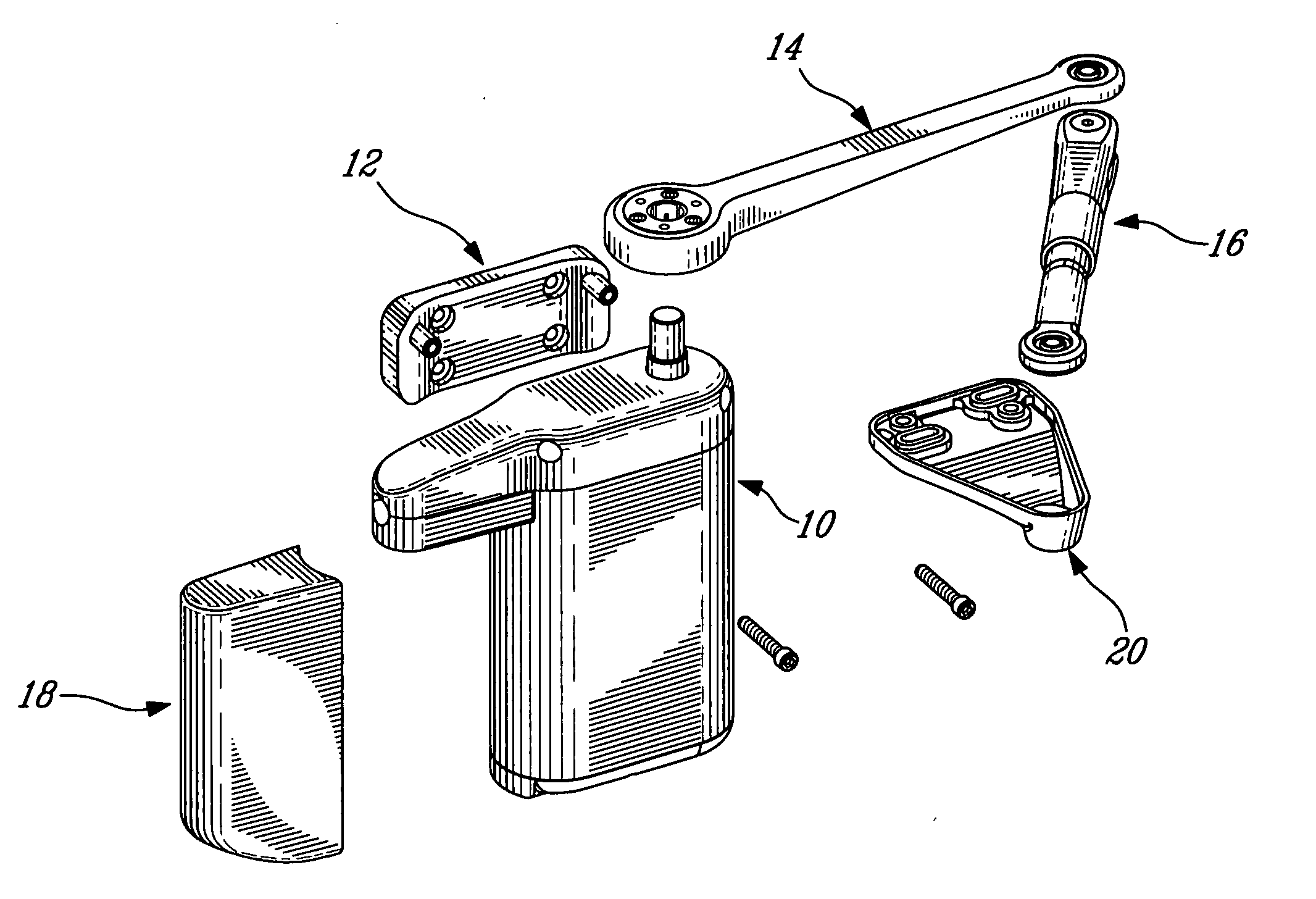
[0029] As illustrated in FIG. 3, a door operator assembly of the present invention comprises an operator unit 10 and a linkage.

[0030] The operator unity 10 is connected to a power storage pack 18 and mounted to a first position, relative to a door (not shown in FIG. 3), by a first mounting bracket 12. The linkage connects the operator unit 10 and a second position, relative to the door, the linkage being mounted at this second position by second mounting bracket 20.

[0031] The first mounting bracket 12 comprises two posts for example, and is of reduced dimensions, allowing an easy mounting.

[0032] As illustrated in FIG. 4, the operator unit 10 comprises an output drive unit 22, an input drive unit with controls 24, a cover 26 and a control cover 28.

[0033] The cover 26 may be used to provide a finished look to the door operator assembly. It is a non-structural member, and may be e...


PUM


Abstract

A door operator assembly, comprising an operator unit mounted to a first position, relative to the door, by a first mounting bracket; and an arm linkage connecting the operator unit and a second position, relative to the door; the arm linkage being mounted at the second position by a second mounting bracket.

Description

CROSS REFERENCE TO RELATED APPLICATIONS [0001] This application claims priority on U.S. provisional application No. 60 / 751,623, filed on Apr. 13, 2005. All documents above are herein incorporated by reference.FIELD OF THE INVENTION [0002] The present invention relates to door operators. More specifically, the present invention is concerned with a door operator assembly. BACKGROUND OF THE INVENTION [0003] Low energy door operators as illustrated in FIGS. 1 and 2 are typically used as manual doors. The door opens automatically by an action such as pressing an activation switch. [0004] Installation of a low energy door operator is usually very expensive, since a typical installation requires an installer attaching a header to the frame of the door, which often requires custom mounting work, installing the operator in the header and installing door arms. Then, a licensed electrician is required to provide power to the door operator. The installer then has to return to complete “tune-in”...

Claims


Application Information

Patent Timeline
Patent Type & Authority Applications(United States)
IPC IPC(8): E05B3/00E05F15/60
CPCE05F1/105E05F15/70E05Y2201/41E05Y2201/604E05Y2201/624E05Y2201/686E05Y2201/72E05Y2400/302E05Y2400/36E05Y2400/614E05Y2800/112E05Y2800/113E05Y2800/22E05Y2800/252E05Y2800/372E05Y2900/132E05F3/227H02J7/14E05F15/12E05F15/60E05F15/611E05F15/63E05F3/224Y10T292/57
Inventor HASS, BRIAN
Owner YALE SECURITY
Why Eureka
Try Eureka