Electromagnetic relay

a technology of electromagnetic relays and relays, applied in the field of electromagnetic relays, can solve the problems of occupying only a small space, affecting the performance of the relay, and affecting the performance of the relay, and achieve the effect of satisfying performan

Active Publication Date: 2006-11-02
RADIALL SA
View PDF2 Cites 20 Cited by
  • Summary
  • Abstract
  • Description
  • Claims
  • Application Information

AI Technical Summary

Benefits of technology

[0043] The stack of printed circuit cards can form a stripline type structure enabling satisfactory performance to be obtained in the high frequenc...

Problems solved by technology

Since the rotor needs to be capable of being driven alternately in rotation and in translation, that relay presents a structure that is relatively complex, which can lea...

Method used


Image

  • Electromagnetic relay
  • Electromagnetic relay
  • Electromagnetic relay

Examples


Embodiment Construction

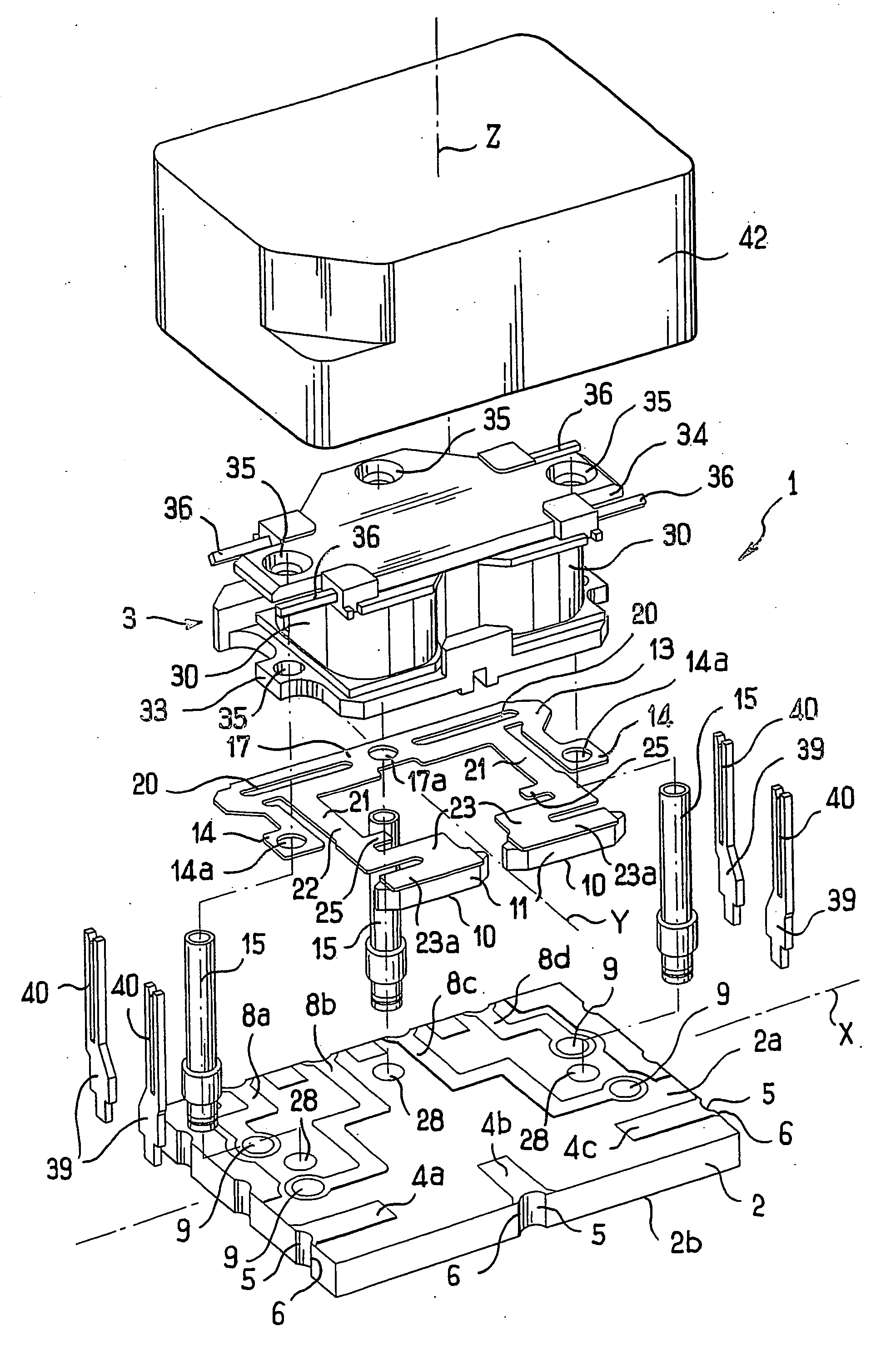
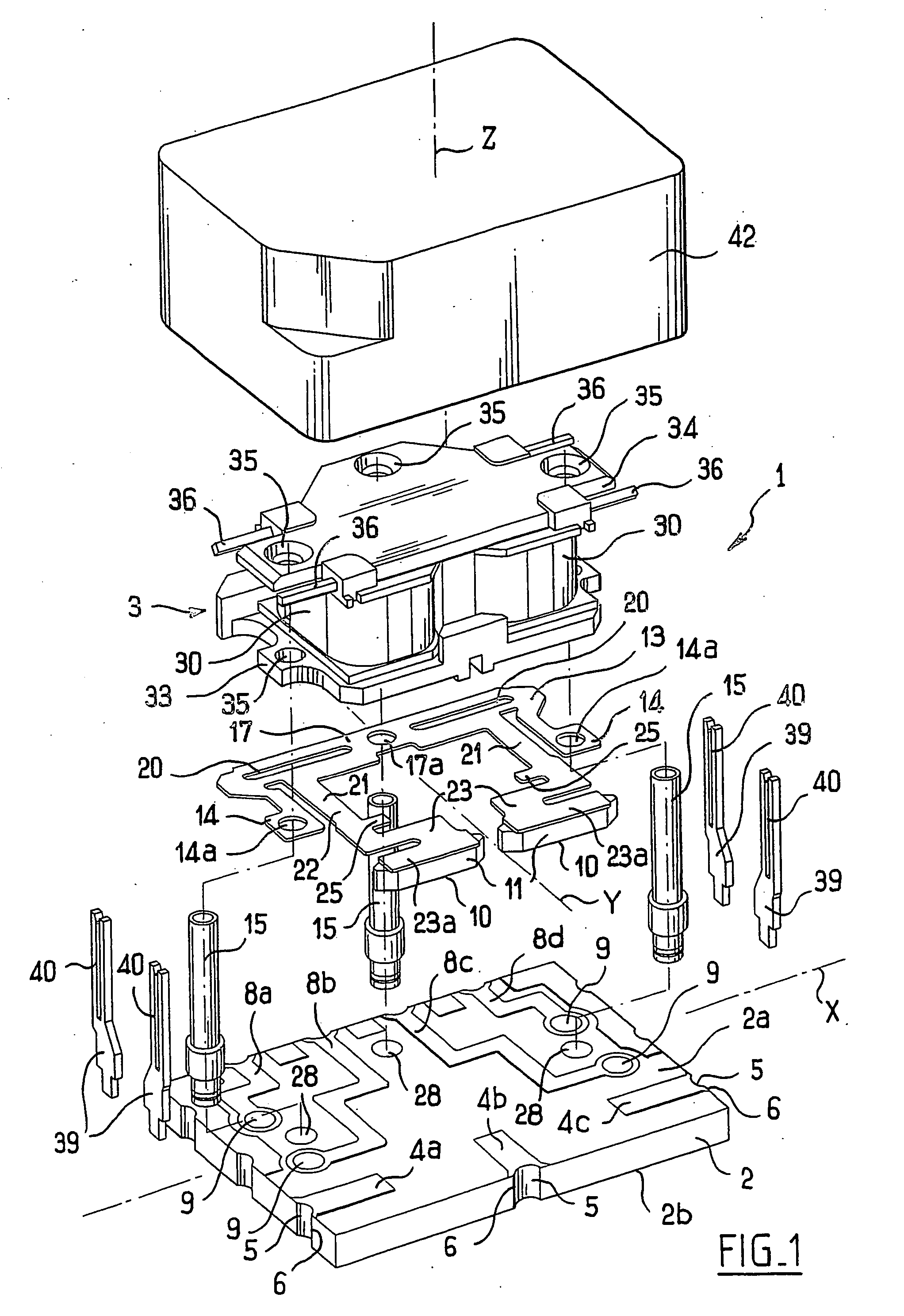
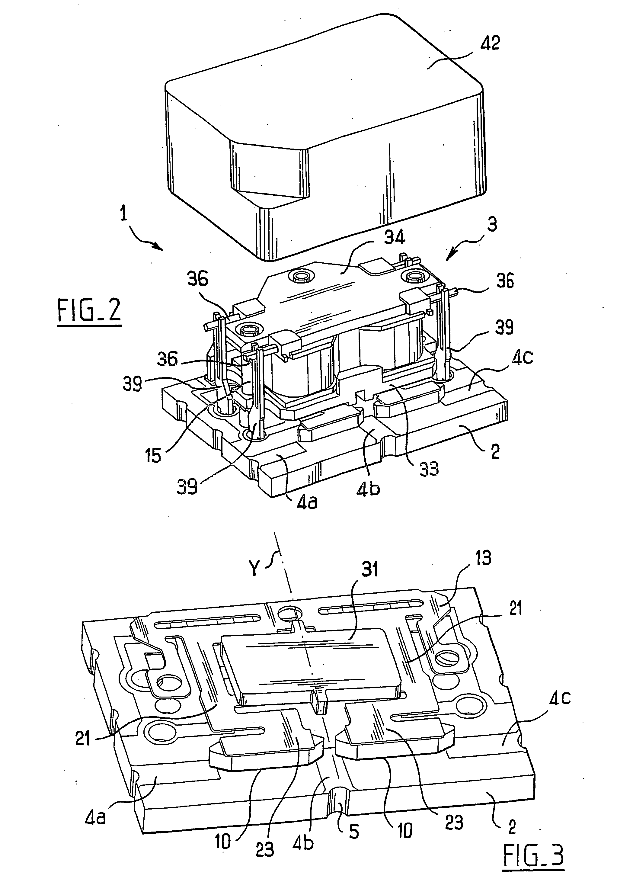
[0079]FIG. 1 shows an electromagnetic relay 1 in accordance with the invention, comprising a base 2 constituted by a printed circuit card made on the basis of epoxy glass or ceramic, and an actuator 3 suitable for being mounted on the printed circuit card 2.

[0080] The card extends in a plane defined by two perpendicular axes X and Y.

[0081] In the example described, the card 2 has three conductor tracks 4a, 4b, and 4c on its top face 2a with the two tracks 4a and 4b forming a first pair of switch accesses and the two tracks 4b and 4c forming a second pair of switch accesses.

[0082] Each of the conductor tracks 4a-4c is connected at one end to a conductive strip 5 formed by plating metal on a setback 6 formed in an edge face of the card 2.

[0083] In the example described, the setbacks 6 are in the form of half-cylinders of axis Z perpendicular to the plane of the card 2. In a variant, the setbacks 6 could be in the form of quarter-cylinders. In another variant, the conductive strips...


PUM


Abstract

The present invention relates to an electromagnetic relay comprising: a base comprising at least one printed circuit card, which card has at least two conductor tracks forming respective switch accesses; at least one conductive contact element movable between a closed position in which it presses against said two conductor tracks in order to establish an electrical connection between them, and an open position in which the contact element is spaced apart from at least one of said two tracks; a contact element support, the support comprising at least one flexible arm carrying the contact elements; and an actuator mounted on the printed circuit card, and comprising at least one coil constituted by a winding of electric wires; wherein the support includes at least one portion, in particular a portion in the form of a tongue, on which a moving member of the actuator acts in order to move said flexible arm of the support.

Description

[0001] The present invention relates to an electromagnetic relay for use in particular in the high frequency domain. BACKGROUND OF THE INVENTION [0002] U.S. Pat. No. 4,839,619 discloses a relay comprising a substrate, such as a printed circuit card having mounted thereon an assembly comprising a rotor and a magnetic armature carrying an elastomer layer and a dielectric layer. The dielectric layer has conductive strips suitable for switching conductor tracks on the substrate. The rotor can be driven not only in rotation about an axis perpendicular to the plane of the substrate, but it can also be moved axially along said axis. Since the rotor needs to be capable of being driven alternately in rotation and in translation, that relay presents a structure that is relatively complex, which can lead to a relatively high sale cost. That relatively complex structure can also make it more difficult to provide a relay that is compact and occupies only a small amount of space. [0003] U.S. Pat....

Claims


Application Information

Patent Timeline
IPC IPC(8): H01H51/22H01H1/58H01H49/00H01H50/04H01H50/14H01H50/44H01H50/54H01H50/60H05K1/14
CPCH01H1/5805H01H49/00H01H50/043H05K1/141H01H50/443H01H50/548H01H50/60H01H50/14
Inventor JANOT, FABRICEBECAVIN, PATRICEGONIN, PASCAL
Owner RADIALL SA
Why Eureka
Try Eureka