
Method and Apparatus for Polling Transmission Status in a Wireless Communication System

ransmission status technology, applied in the field of methods and apparatus for polling transmission status in a wireless communication system, can solve the problems of system errors, inefficiency transmission speed, and inability to meet the needs of users, etc., to achieve the effect of system errors, and reducing the overall transmission efficiency

Active Publication Date: 2006-11-02
INNOVATIVE SONIC
View PDF11 Cites 10 Cited by
  • Summary
  • Abstract
  • Description
  • Claims
  • Application Information

AI Technical Summary

Benefits of technology

[0010] On the other hand, in UMTS, if the transmitter transmits a Service Data Unit (SDU) and the SDU is retransmitted for a predetermined number of times unsuccessfully, or the transmitter never receives a positive acknowledgement corresponding to the SDU from the receiver after a predetermined period of time, for better transmission efficiency, the transmitter (with an explicit signaling procedure) discards the SDU and transmits a Move Receiving Window (MRW) super-field to the receiver. After the transmitter discards the SDU, PDUs that carry segments of the SDU and / or the Length Indicator indicating the ending position of the SDU are also discarded. Therefore, the transmitter can improve transmission efficiency to reduce system resources wasted on unnecessary retransmission of PDUs and waiting for acknowledgements.

Problems solved by technology

Communications systems of prior art are facing bottlenecks of channel usage overflowing and inefficient transmission speeds.
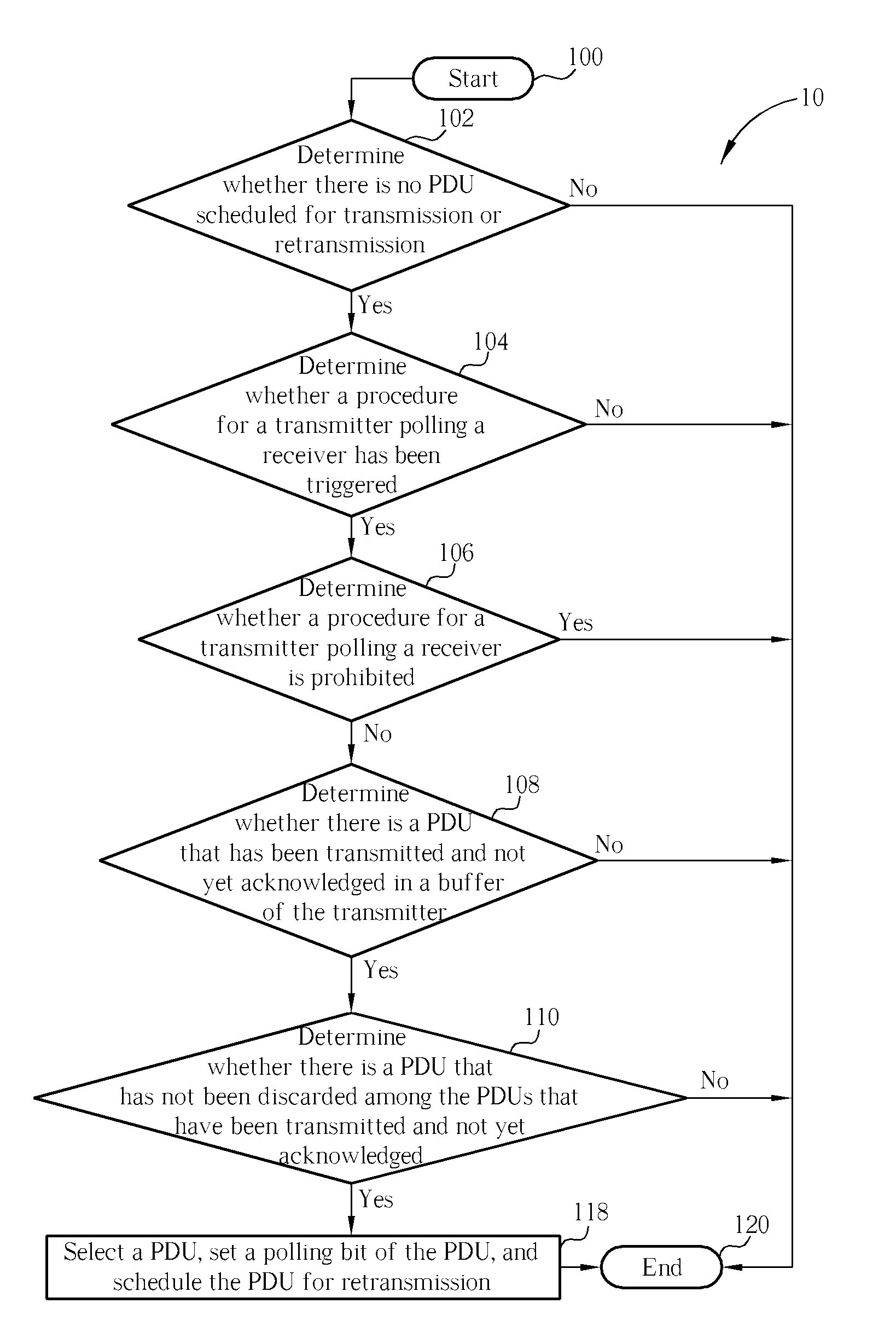
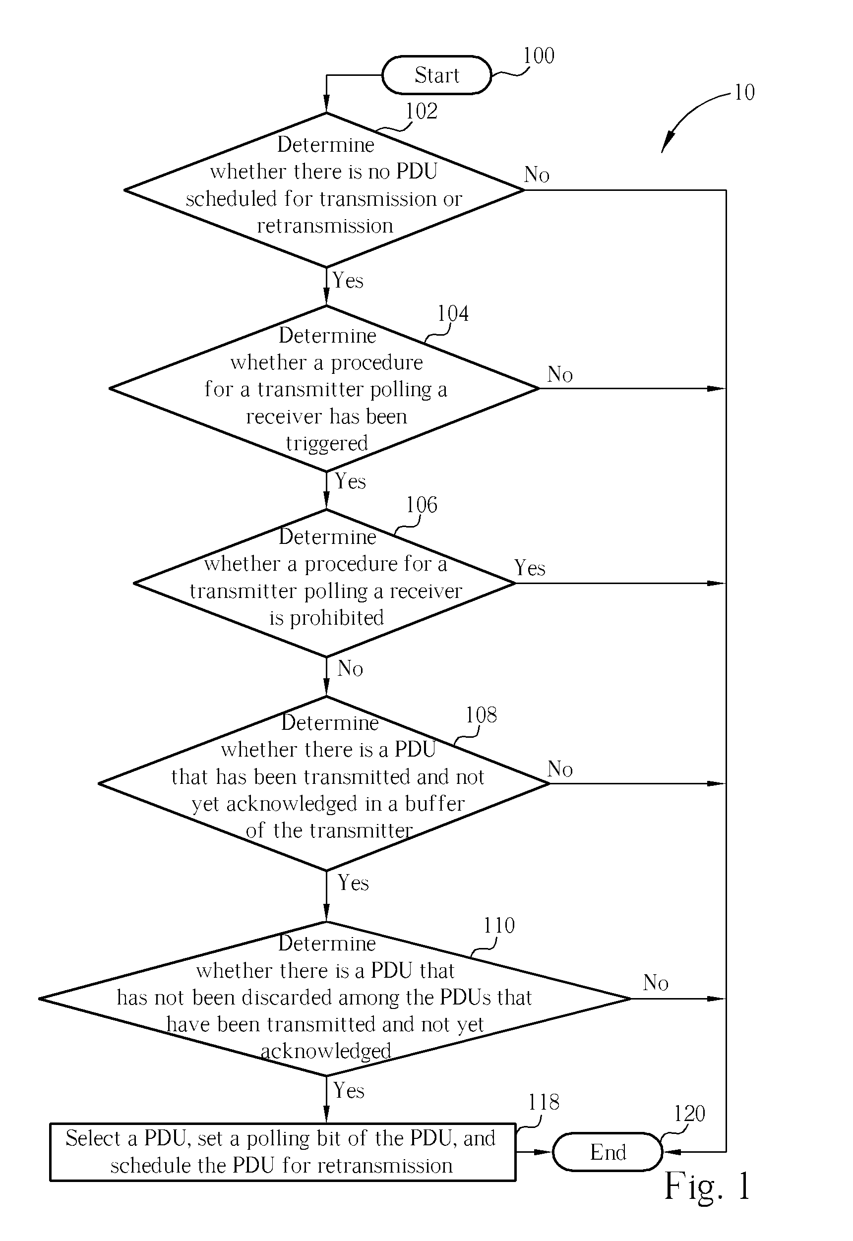
In some cases, all PDUs stored in a buffer of the transmitter are discarded before being acknowledged, and an error occurs when selecting a PDU to poll.
However, because the buffer of the transmitter has no PDUs inside, an error occurs since the transmitter cannot successfully select a PDU for polling.
In summary, in the prior art, when all PDUs in the buffer of the transmitter are discarded before being positively acknowledged, the transmitter cannot successfully execute a polling operation, which leads to system errors.
Therefore, an extra operation lowers an overall transmission efficiency and induces system resource wastage.

Method used


Image

  • Method and Apparatus for Polling Transmission Status in a Wireless Communication System
  • Method and Apparatus for Polling Transmission Status in a Wireless Communication System
  • Method and Apparatus for Polling Transmission Status in a Wireless Communication System

Examples


Embodiment Construction

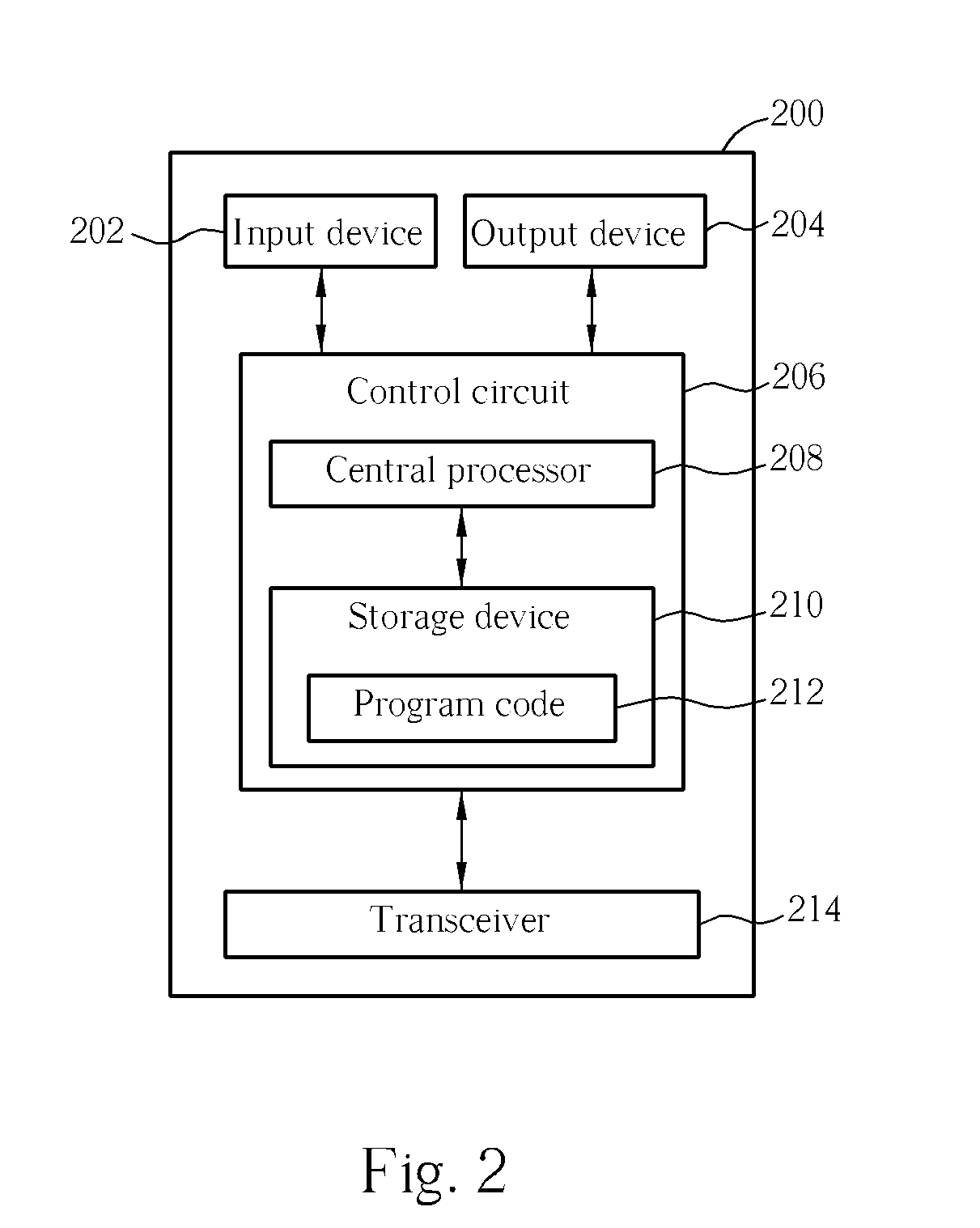
[0018] Please refer to FIG. 2. FIG. 2 is a block diagram of a wireless communications transmission device (transmitter) 200 used in a wireless communications system. The wireless communications system can be a 3rd generation mobile communications system, such as UMTS. For simplicity, FIG. 2 only shows an input device 202, an output device 204, a control circuit 206, a central processor 208, a storage device 210, a program code 212, and a transceiver 214 of the wireless communications transmission device 200. In the wireless communications transmission device 200, the control circuit 206 executes the program code 212 stored in the storage device 210 with the central processor 208, and then controls operations of the wireless communication transmission device 200. The wireless communications transmission device 200 can receive signals input by users through the input device 202, or output signals through the output device 204. The transceiver 214 is used for receiving or transmitting ...


PUM


Abstract

A method for polling transmission status in a wireless communications system includes determining whether a buffer of a transmitter contains at least a packet that has been transmitted, has not been discarded, and has not yet been acknowledged when there is no packet scheduled for transmission or retransmission while a polling procedure is triggered and is not prohibited, selecting a packet in order to transmit a poll, and scheduling the selected packet for retransmission.

Description

CROSS REFERENCE TO RELATED APPLICATIONS [0001] This application claims the benefit of U.S. Provisional Application No. 60 / 594,697, filed Apr. 29, 2005, and included herein by referenceBACKGROUND OF THE INVENTION [0002] 1. Field of the Invention [0003] The present invention is a method and apparatus for polling transmission status in a wireless communications system, in particular a method and apparatus for avoiding a transmitter being unable to successfully execute a polling procedure to a receiver and avoiding the transmitter executing unnecessary polls. [0004] 2. Description of the Prior Art [0005] With the coming of the information age, requirements of mobile voice, data communications, and various mobile services increase each day. Communications systems of prior art are facing bottlenecks of channel usage overflowing and inefficient transmission speeds. Therefore, the third generation mobile communication was developed to have better usage of the frequency spectrum and higher-s...

Claims


Application Information

Patent Timeline
Patent Type & Authority Applications(United States)
IPC IPC(8): H04J3/16H04W74/06H04W84/18
CPCH04L1/1685H04L1/1832H04L1/187H04L12/6418H04L47/10H04L47/14H04W84/18H04L47/263H04L47/27H04L47/283H04L47/32H04W74/06H04L47/22H04L9/40H04W8/04
Inventor JIANG, SAM SHIAW-SHIANG
Owner INNOVATIVE SONIC
Learn More