

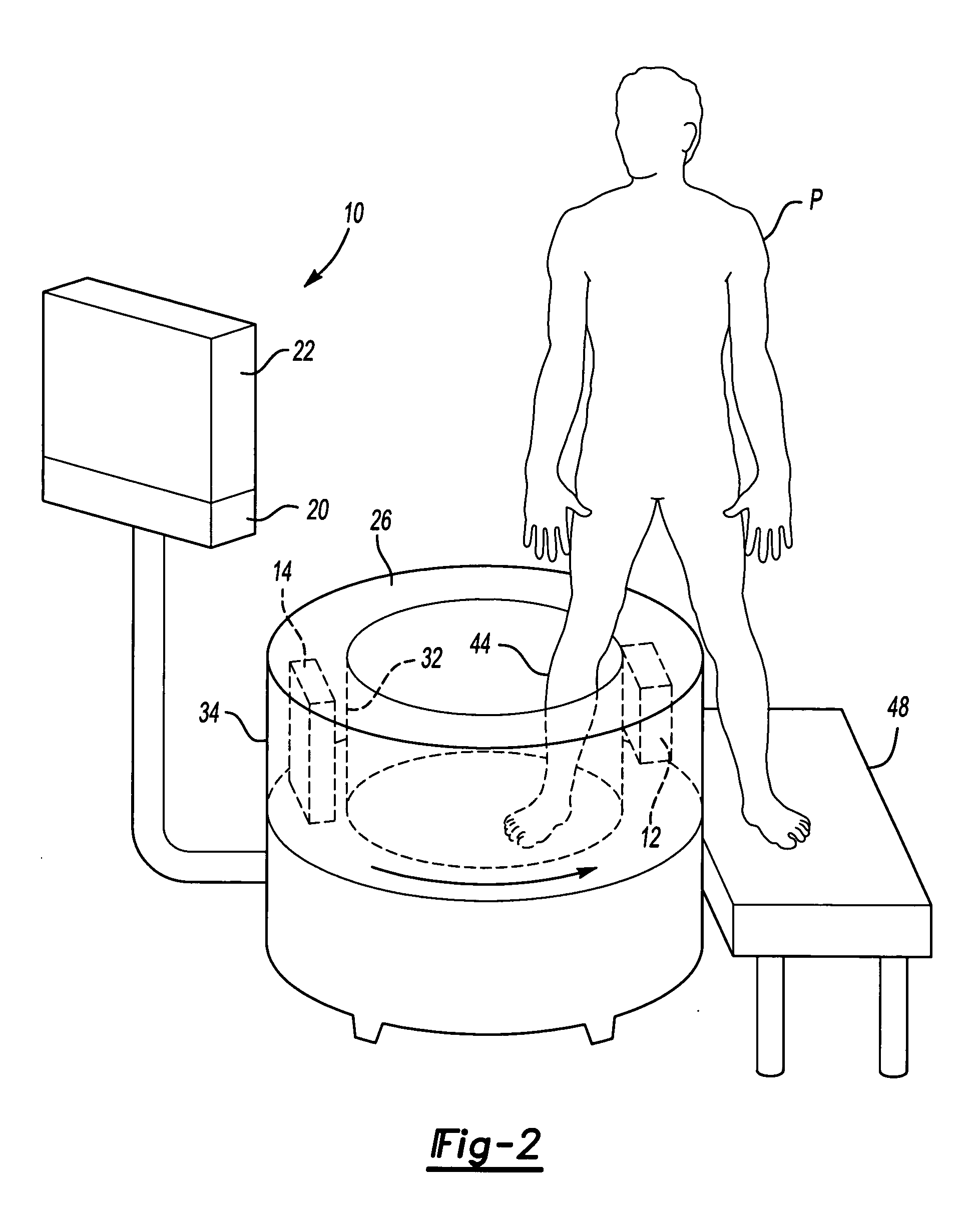
CT scanner for lower extremities
a ct scanner and lower extremity technology, applied in the direction of instruments, patient positioning for diagnostics, applications, etc., can solve the problems of inability to locate a doctor's office, large ct scanners, and difficulty in diagnosing foot and ankle injuries and problems, and achieve the effect of reducing the number of patients
- Summary
- Abstract
- Description
- Claims
- Application Information
AI Technical Summary
Problems solved by technology
Method used
Image

Examples
Embodiment Construction
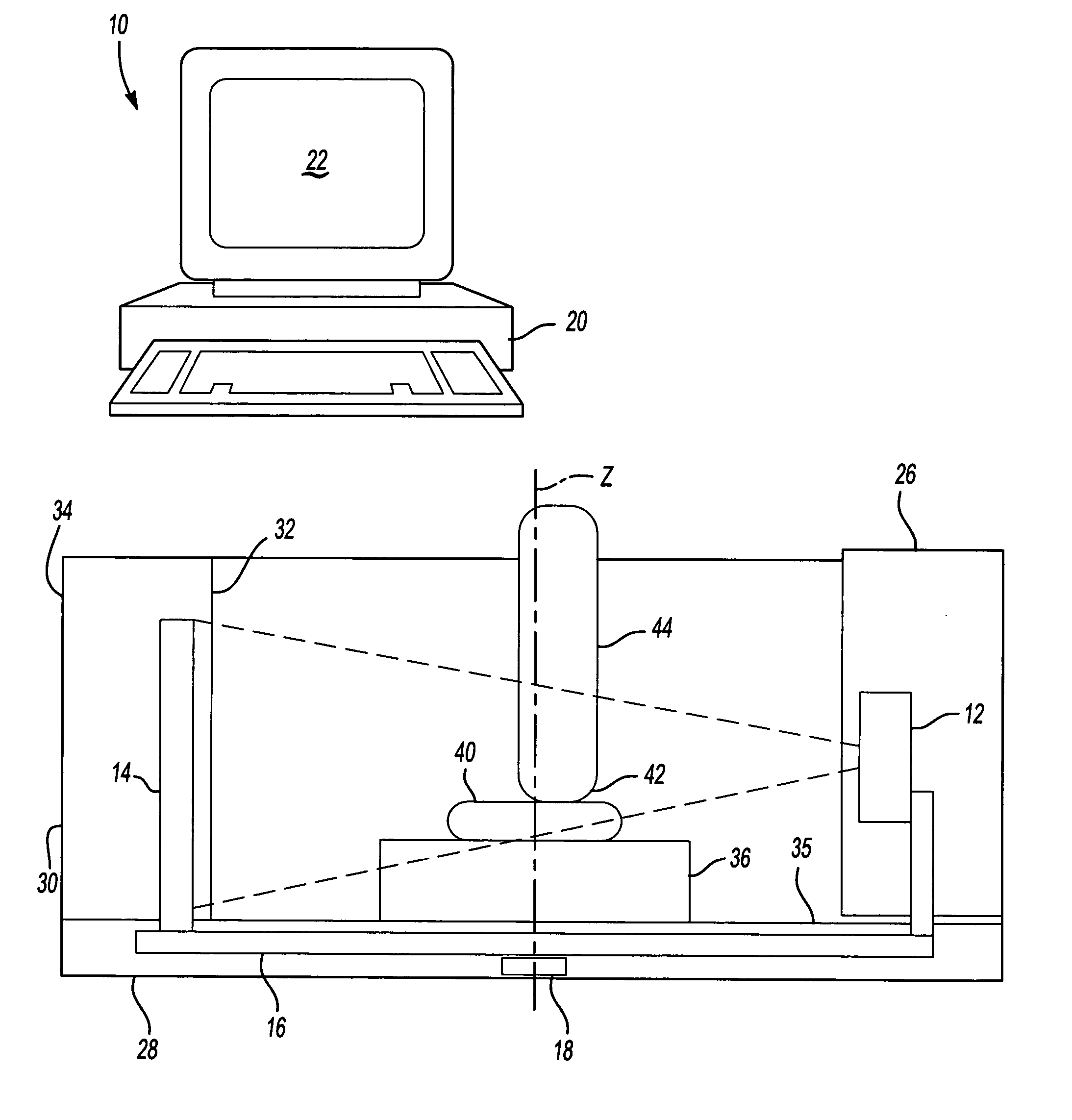
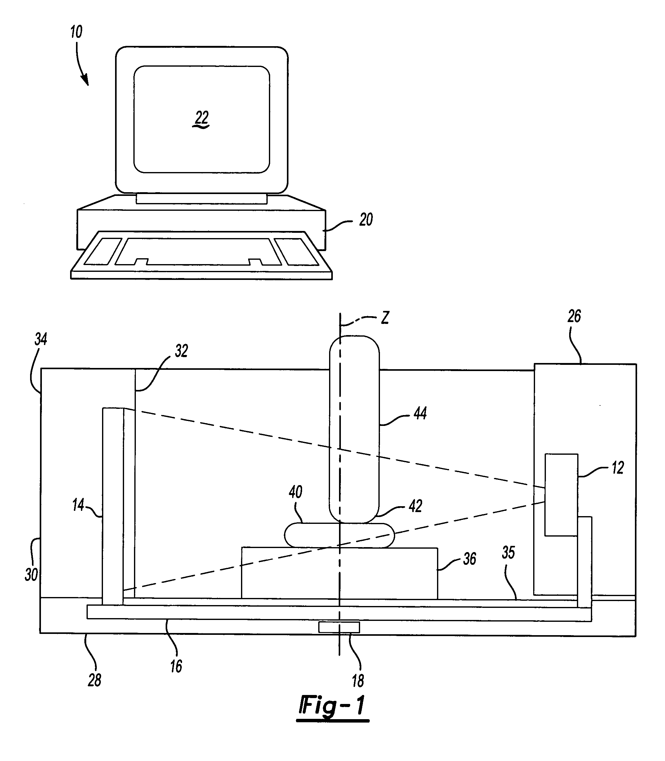
[0013] A CT scanning system 10 according to one embodiment of the present invention is shown schematically in FIG. 1. The CT scanning system 10 includes an X-ray source 12 mounted opposite an X-ray detector 14 on a gantry 16. The X-ray source 12 is preferably a cone-beam X-ray source and the detector 14 is preferably a flat panel detector. The flat panel detector 14 would have a converter for converting X-rays into visible light and an array of photo detectors behind the converter. Any suitable X-ray source 12 and detector 14 could be utilized, as the invention is independent of the specific technology used for the CT scanning system 10. Although not shown, a collimator and other known CT components could also be utilized.
[0014] The gantry 16 is rotated about an axis Z by a motor 18 controlled by a computer 20. The computer also controls the X-ray source 12 and receives X-ray images from the detector 14. The computer 20 also includes the CT reconstruction algorithm that converts a ...
PUM
| Property | Measurement | Unit |
|---|---|---|
| CT scan | aaaaa | aaaaa |
| angle | aaaaa | aaaaa |
| gravity | aaaaa | aaaaa |
Abstract
Description
Claims
Application Information