Canned pump
a magnetic pump and pump body technology, applied in the direction of positive displacement liquid engines, pump components, fluid engines, etc., can solve the problems of frequent failure of liquid feeding, no lubricating oil can be used at the bearing sections of the impeller shaft, etc., to achieve excellent durability, low maintenance cost, and low friction coefficient
- Summary
- Abstract
- Description
- Claims
- Application Information
AI Technical Summary
Benefits of technology
Problems solved by technology
Method used
Image

Examples
first embodiment
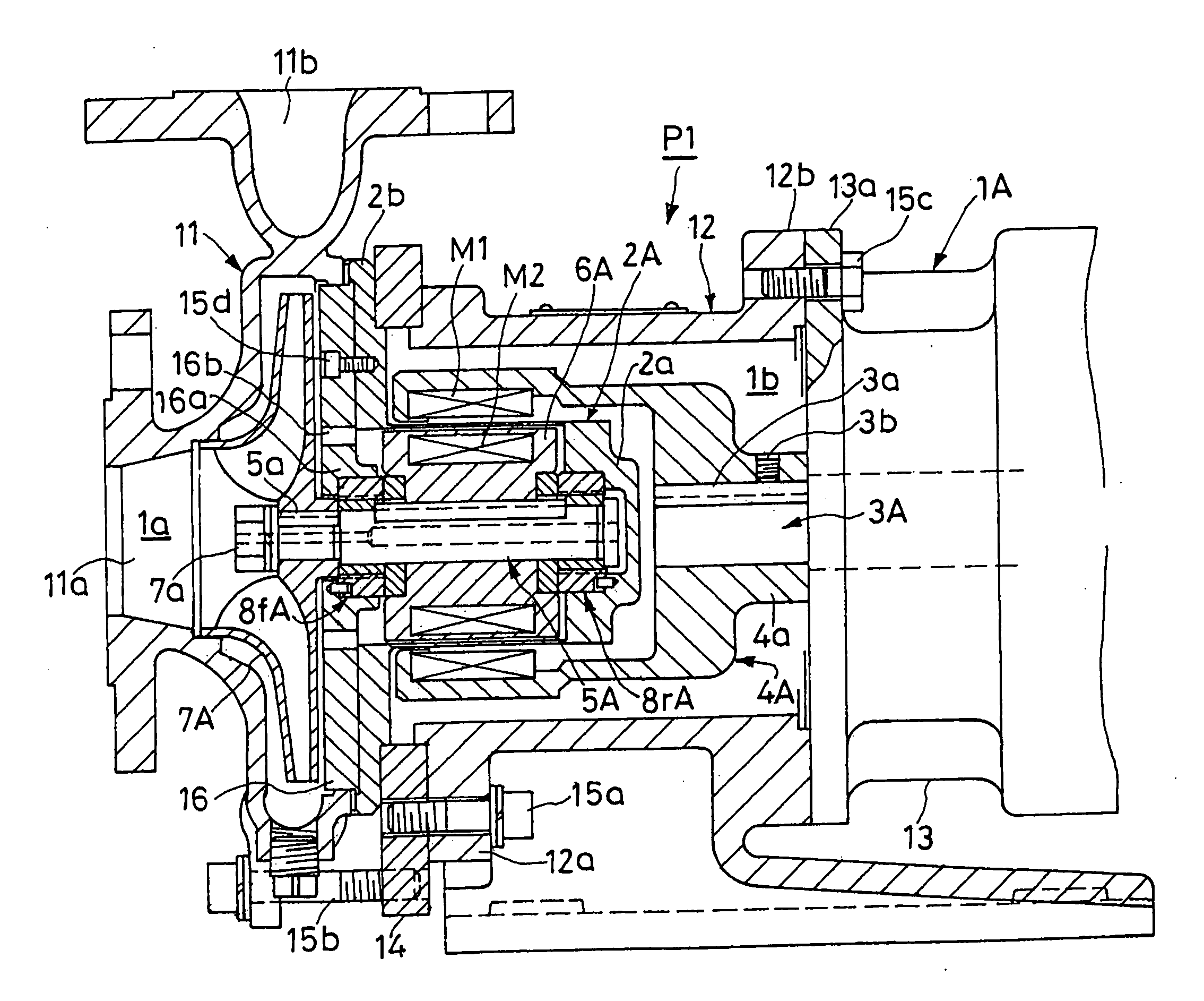
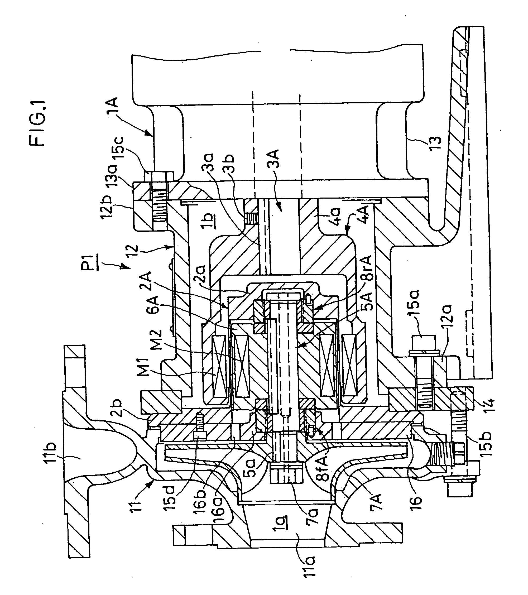
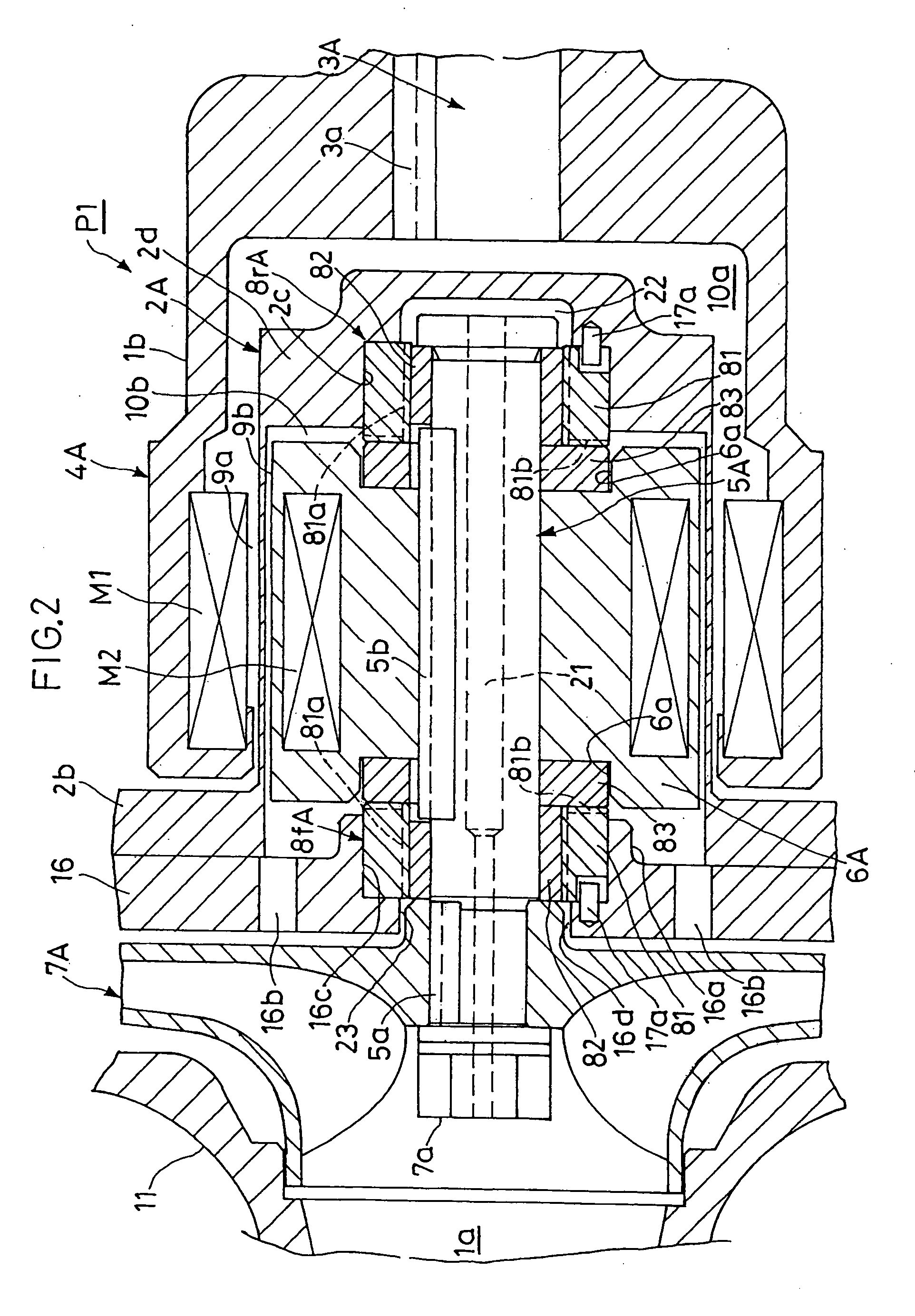
[0020] As shown in FIG. 1 and FIG. 2, the casing 1A of a magnet pump P1 in accordance with the first embodiment comprises a front casing member 11 equipped with a liquid suction port 11a and a liquid delivery port 11b, a cylindrical intermediate casing member 12 connected to this front casing member 11 at the front end flange section 12a thereof via a ring-shaped flange member 14 and bolts 15a, and 15b, and a cylindrical rear casing member 13 connected to the rear end flange section 12b of this intermediate casing member 12 at the front end flange section 13a thereof via bolts 15c. The inside of the casing 1A is divided into a pump chamber 1a on the side of the front casing member 11 and a magnetic coupling chamber 1b on the side of the intermediate casing member 12 by a partition plate 16 interposed between the front casing member 11 and the intermediate casing member 12. Furthermore, a pump drive section comprising a motor, not shown, is provided on the side of the rear casing mem...
second embodiment
[0032] The casing 1B of a magnet pump P2 in accordance with a second embodiment shown in FIG. 4 comprises a front casing member 31 equipped with a liquid suction port 31a and a liquid delivery port 31b, a cylindrical intermediate casing member 32 connected to this front casing member 31 at the front end flange section 32a thereof via bolts 15e, and a cylindrical rear casing member 33 connected to the rear end flange section 32b of this intermediate casing member 32 at the front end flange section 33a thereof via bolts 15f. In addition, inside the casing 1B, the front end flange section 2e of a cylindrical can 2B having a bottom is held between the opposed end faces of the front casing member 31 and the intermediate casing member 32, whereby the cylindrical can 2B is disposed with the bottom section 2f directed rearward. Furthermore, the inside of the casing 1B is divided by this can 2B into a drive-side space 20a on the outside of the can 2B and a driven-side space 20b extending fro...
third embodiment
[0039] The casing 1C of a canned motor pump P3 in accordance with a third embodiment shown in FIG. 5 comprises a front casing member 51 equipped with a liquid suction port 51a and a liquid delivery port 51b, a partition plate 52 connected to this front casing member 51 at the peripheral portion thereof via bolts 15g, a nearly cylindrical rear casing member 53 connected to this intermediate partition plate 52 at the front end flange section 53a thereof via bolts 15h, a rear end plate 54 connected to the rear end of this rear casing member 53 at the peripheral section thereof via bolts 15i, and a support base 55 connected to the lower section of the rear casing member 53 via bolts 15j.
[0040] In addition, the rear casing member 53 and the rear end plate 54 constitute a cylindrical can 2C having a bottom, and the inside of this can 2C serves as a rotor chamber 60. At the central section inside the rotor chamber 60, an impeller shaft 5C journaled on the partition plate 52 and the rear e...
PUM
 Abstract
Description
Claims
Application Information
 - R&D Engineer
- R&D Manager
- IP Professional
- Industry Leading Data Capabilities
- Powerful AI technology
- Patent DNA Extraction
Browse by: Latest US Patents, China's latest patents, Technical Efficacy Thesaurus, Application Domain, Technology Topic.
© 2024 PatSnap. All rights reserved.Legal|Privacy policy|Modern Slavery Act Transparency Statement|Sitemap