
Spinal pedicle screw assembly

a technology of screw and screw body, which is applied in the field of spine screw assembly, can solve the problems of spinal fixation, insufficient locking and restraining force to fix a disordered spine,

Inactive Publication Date: 2006-11-02
SOLCO BIOMEDICAL
View PDF16 Cites 261 Cited by
  • Summary
  • Abstract
  • Description
  • Claims
  • Application Information

AI Technical Summary

Benefits of technology

"The present invention provides a spinal pedicle screw assembly that prevents the spine rod from loosening even under strong external force. The assembly includes a head-coupling element, a screw rod, and a tightening screw. The head-coupling element has female screw threads in its rod-receiving channel and male screw threads on its inside. The screw rod has male screw threads and is fixedly inserted into the pedicle by the male screw threads. The tightening screw has male screw threads for engaging the female screw threads of the rod-receiving channel to fix the spine rod. A restraining plate is positioned between the upper end of the connecting bore and the spherical head to restrain the spherical head from moving. The assembly also includes a final fixing screw for preventing the spherical head from disconnecting from the head-coupling element. The technical effects of the invention are improved stability and reliability of spinal fixation, reduced risk of complications, and improved patient outcomes."

Problems solved by technology

However, such spinal pedicle screw assembly suffers such drawback that an external force may loosen the externally locking screw member, thus resulting in an insufficient locking and restraining force to fix a disordered spine.
However, this also cannot adequately compensate for an external force, so that the bodily motion causes the screw member to loosen from the internally engaging head-coupling element after a long time, thus producing a problem in the spinal fixation.

Method used


Image

  • Spinal pedicle screw assembly
  • Spinal pedicle screw assembly
  • Spinal pedicle screw assembly

Examples


Embodiment Construction

[0028] Throughout descriptions in connection with the drawings, same reference numerals are used to represent same functional parts for convenience's sake. In addition, there are omitted detailed descriptions of the conventional parts not required to comprehend the technical concept of the present invention.

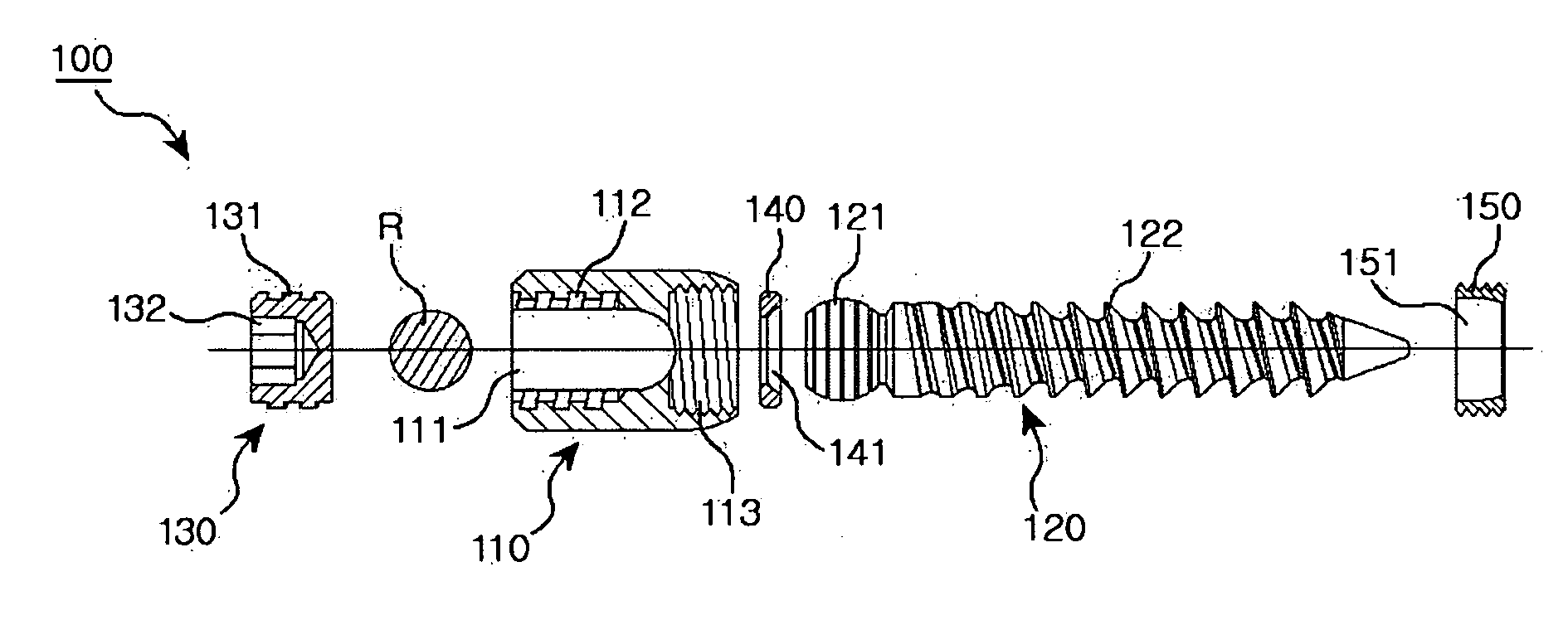
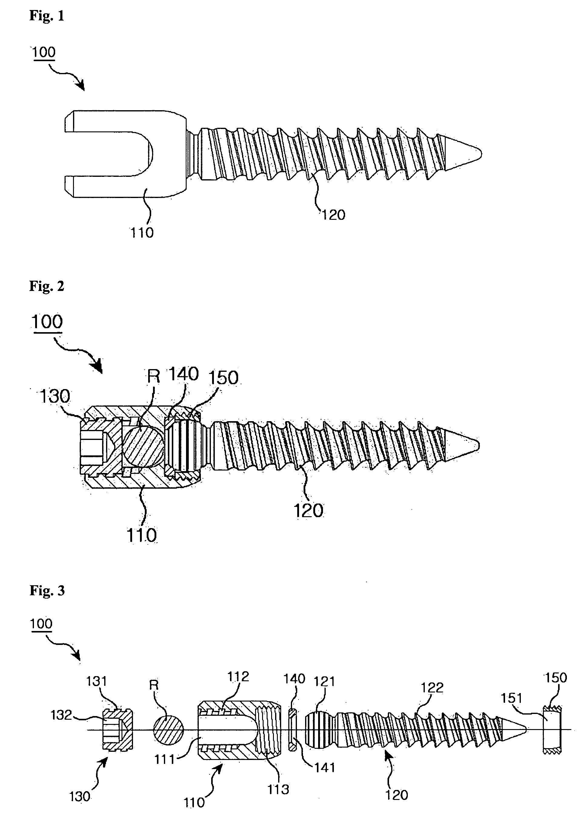
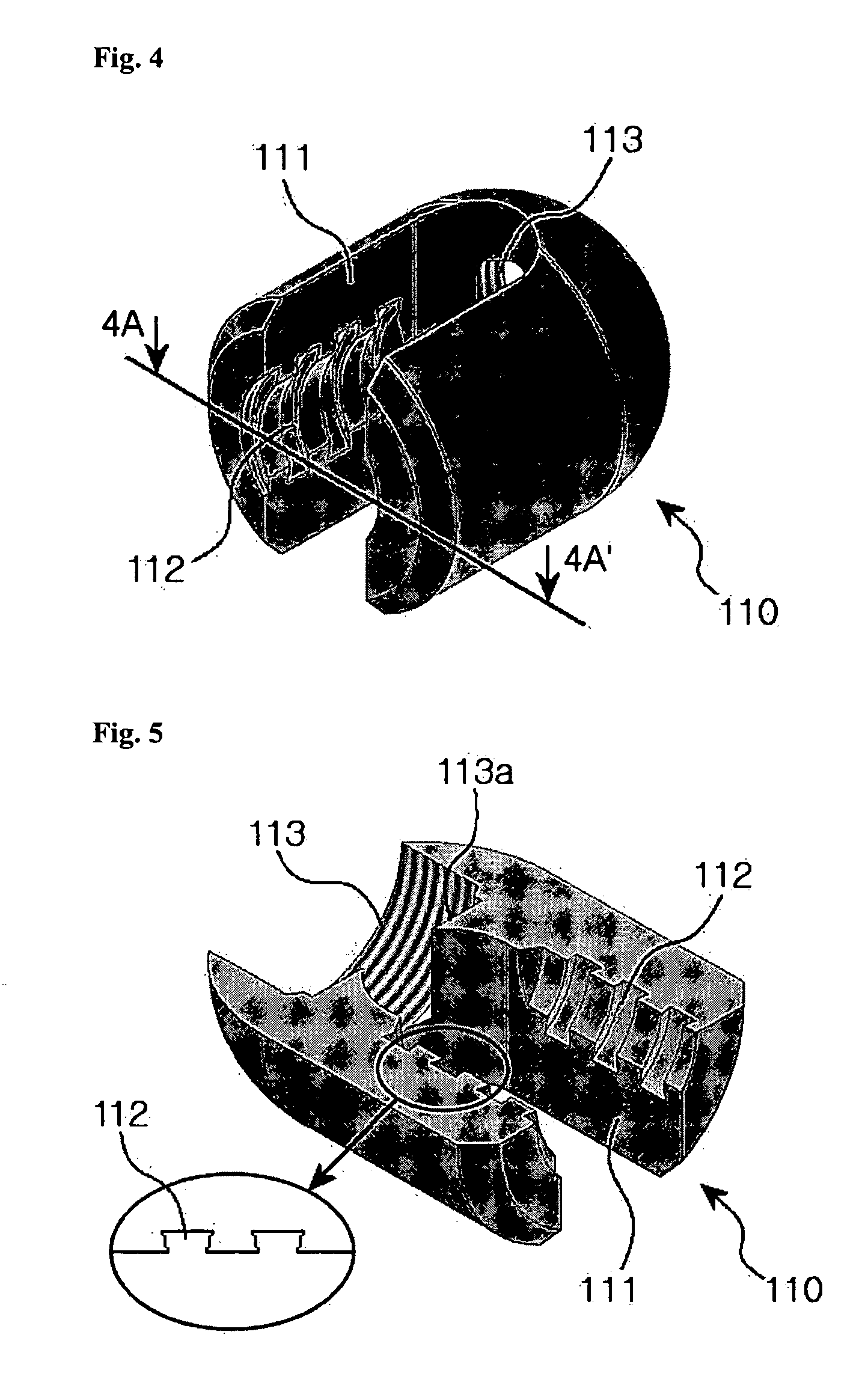
[0029] Referring to FIGS. 1 to 3, a spinal pedicle screw assembly 100 according to an embodiment of the present invention includes a head-coupling element 110 with an upper and a lower end for receiving a spine rod R, a screw rod 120 having an upper and a lower end and a spherical head 121 integrally formed with the upper end thereof, and a tightening screw 130 for fixing the spine rod R in the head-coupling element 110. The head-coupling element 110 has a rod-receiving channel 111 opening toward the upper end for receiving the spine rod R, female screw threads 112 formed on the inside of the rod-receiving channel 111, and a connecting bore 113 of a given size extending through ...


PUM


Abstract

Disclosed is a spinal pedicle screw assembly including a spinal pedicle screw cooperating with a spine rod for fixing a spine, which includes: a head-coupling element having an upper and a lower end, a rod-receiving channel opening toward the upper end for receiving the spine rod, female screw threads formed on the inside of the rod-receiving channel, and a connecting bore of a given size extending through the lower end, the connecting bore having an upper end toward the rod-receiving channel and an opposite lower end; a screw rod having an upper and a lower end, a spherical head integrally formed with the upper end thereof for being inserted into the connection bore, and male screw threads formed on the periphery of the screw rod between the spherical head and lower end thereof, the screw rod being fixedly inserted into the pedicle by means of the male screw threads thereof; a tightening screw having a periphery formed with male screw threads for engaging the female screw threads of the rod-receiving channel so as to fix the spine rod in the head-coupling element; and a final fixing screw threadedly engaged by the connecting bore for preventing the spherical head from disconnecting from the head-coupling element.

Description

BACKGROUND OF THE INVENTION [0001] 1. Field of the Invention [0002] The present invention relates to a spinal pedicle screw assembly including a spinal pedicle screw that cooperates with a spine rod for stabilizing a spine. In this technical field, the term spine rod usually means an orthopedic rod used in the spinal fixation technique for immobilizing the spine. [0003] 2. Description of the Related Art [0004] The spinal column is a highly complex system of bones and connective tissues that provides support for the body and protects the delicate spinal cord and nerve root. The spinal column includes a series of vertebrae stacked one atop the other, each vertebral body including an inner or central portion of relatively weak cancellous bone and an outer portion of relatively strong cortical bone. [0005] The spinal column disorders are usually cured in two ways, one of which is an indirect method of physical therapy, and the other is a direct method using an artificial fixation device...

Claims


Application Information

Patent Timeline
Patent Type & Authority Applications(United States)
IPC IPC(8): A61F2/30
CPCA61B17/7037A61B17/7032
Inventor AHN, SAE YOUNGLIM, JAE KWANCHOI, JONG MYEONLEE, HOONLIM, CHANG SOOKIM, SEO KONKIM, SE RYEONGKIM, HOON
Owner SOLCO BIOMEDICAL
Learn More