
Direct compression wind energy system and applications of use

a technology of wind energy and direct compression, applied in the field of can solve the problems of increasing the cost of such cables, affecting the cost of wind energy, and imposing costly and/or burdensome requirements on the deliverer of such varying energy, etc., and achieve the effect of improving the wind energy and storage system

Undetermined Publication Date: 2006-11-09
GENERAL COMPRESSION
View PDF0 Cites 40 Cited by
  • Summary
  • Abstract
  • Description
  • Claims
  • Application Information

AI Technical Summary

Benefits of technology

The system achieves a high power-to-weight ratio, enabling efficient energy storage and transmission, minimizing the need for electrical generators offshore, and allows for peak demand energy sales, enhancing the economic value of wind energy while reducing transmission costs.

Problems solved by technology

This means the electrical energy harvested from the areas of abundant wind must be transmitted to areas of great demand, often requiring the transmission of power over long distances.
Transmission and market access constraints can significantly affect the cost of wind energy.
Varying and relatively unpredictable wind speeds affect the hour to hour output of wind plants, and thus the ability of power aggregators to purchase wind power, such that costly and / or burdensome requirements can be imposed upon the deliverer of such varying energy.
The cost of such cables increases with the distance from shore.
As in the case of land-based windplants with distant markets, there will be greatly increased costs as the offshore windpower facility moves farther from the shore and the load centers.
In fact, the increase in costs over longer distance may be expected to be significantly higher in the case of offshore windplants.

Method used


Image

  • Direct compression wind energy system and applications of use
  • Direct compression wind energy system and applications of use
  • Direct compression wind energy system and applications of use

Examples


Embodiment Construction

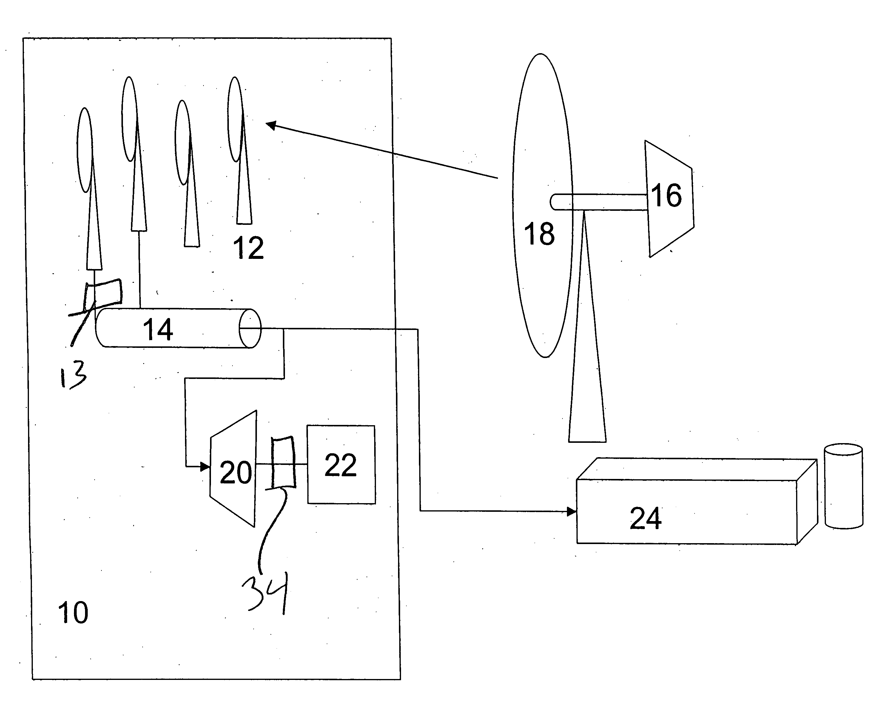
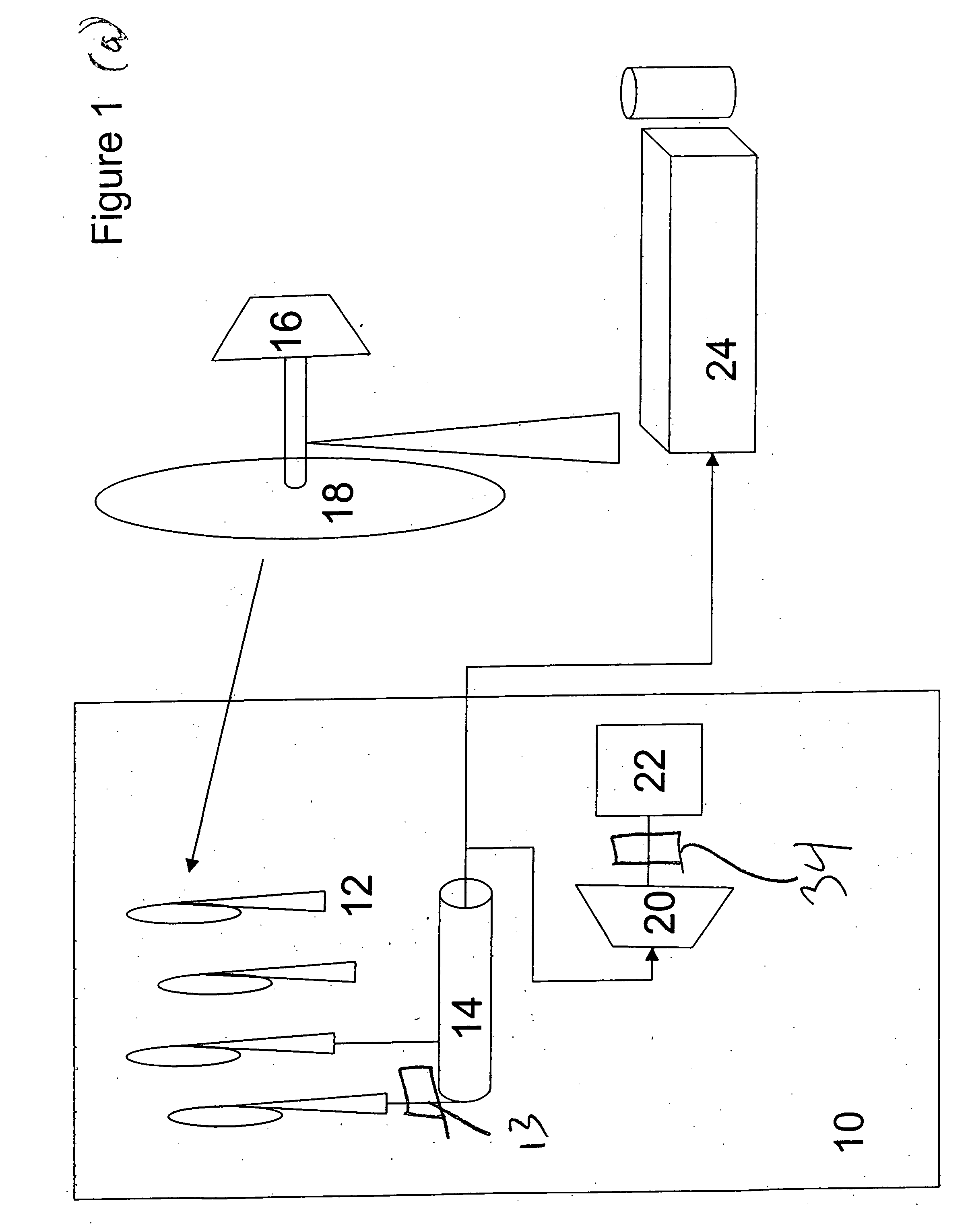
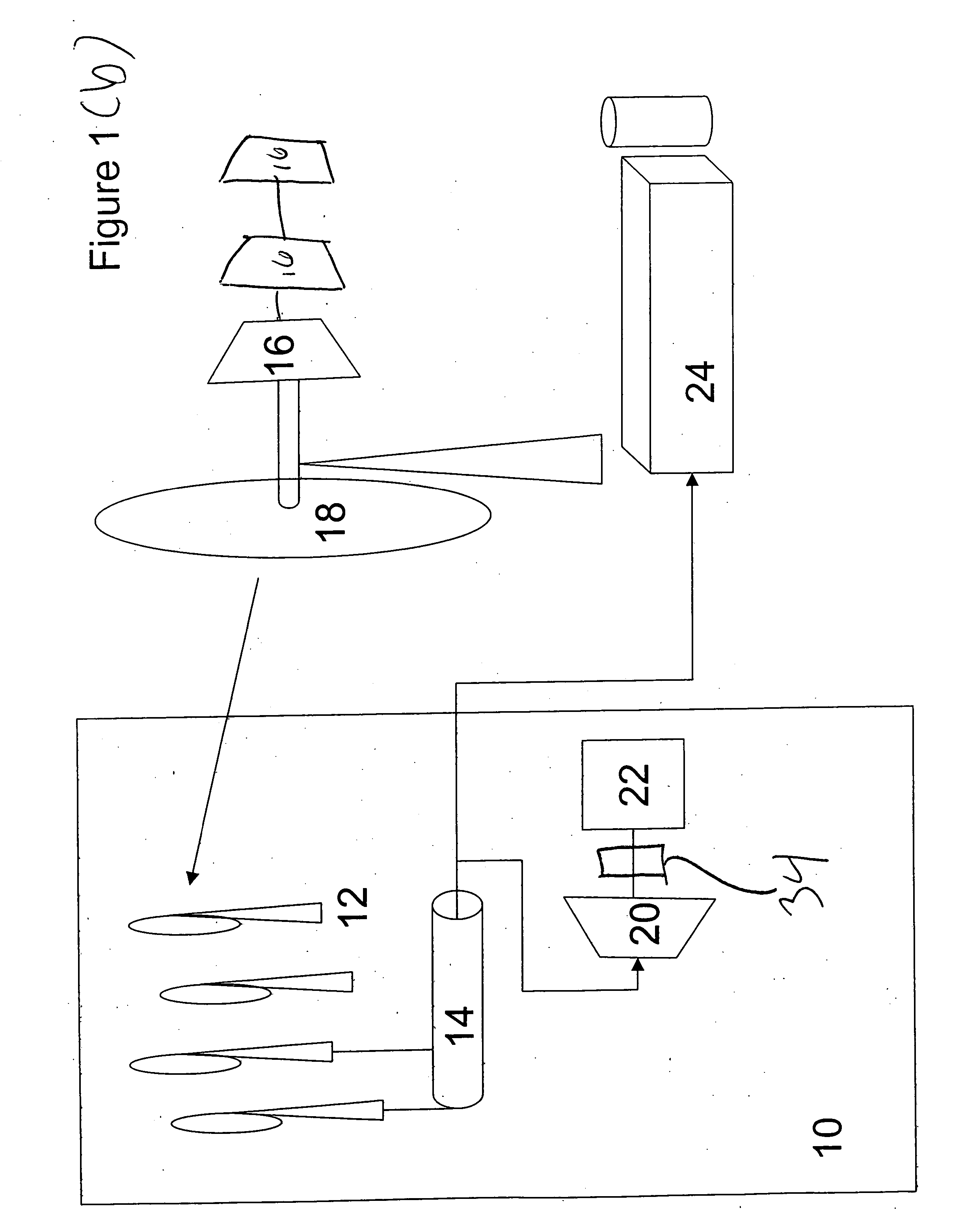
[0018] Referring to FIG. 1(a), one embodiment of the present invention is a wind energy generating and storage system, generally denoted as 10. A plurality of direct compression wind turbine stations 12 are provided. An intercooler 13 can be included. Direct compression is direct rotational motion of a shaft or a rotor coupled to one or more compressors 16. A storage device 14 is coupled to at least a portion of the wind turbine stations 12. At least a first toroidal intersecting vane compressor 16 is coupled to the storage device to compress or liquefy air. The compressor 16 has a fluid intake opening and a fluid exhaust opening. Rotation of a turbine 18 drives the compressor 16. At least one expander 20 is configured to release compressed or liquid air from the storage device 14. A generator 22 is configured to convert the compressed or liquid air energy into electrical energy.

[0019] In various embodiments, the compressor 16 operates at a pressure of about, 10 to 100 atmospheres ...


PUM


Abstract

A wind energy generating and storage system has a plurality of direct compression wind turbine stations. A storage device is coupled to at least a portion of the wind turbine stations. At least a first compressor is coupled to the storage device to compress air. At least one expander is configured to release compressed air from the storage device. A generator is configured to convert compressed air energy into electrical energy. The system has a top-of-tower power to weight ratio greater than 1 megawatt / 10 tons excluding the blades and rotor.

Description

RELATED APPLICATIONS [0001] This application is a continuation-in-part of U.S. Ser. No. 10 / 744,232, filed Dec. 22, 2003, which application is fully incorporated herein by reference.BACKGROUND [0002] 1. Field of the Invention [0003] This invention relates generally to a wind energy and storage system, and more particularly to a wind energy and storage system that has a top-of-turbine power to weight ratio greater than 1 megawatt / 15 tons. [0004] 2. Description of the Related Art [0005] From its commercial beginnings more than twenty years ago, wind energy has achieved rapid growth as a technology for the generation of electricity. The current generation of wind technology is considered mature enough by many of the world's largest economies to allow development of significant electrical power generation. By the end of 2005 more than 59,000 MW of windpower capacity had been installed worldwide, with annual industry growth rates of-greater than 25% experienced during the last five years....

Claims


Application Information

Patent Timeline
Patent Type & Authority Applications(United States)
IPC IPC(8): F01K13/00B63H1/06F03D9/02
CPCF03D9/028Y02E10/72Y02E60/15F05B2210/16F03D9/17Y02P90/50Y02E60/16Y02P70/50Y02E70/30F03D9/28F03D9/25F03D9/007
Inventor INGERSOLL, ERIC
Owner GENERAL COMPRESSION
Learn More