Hydraulic pressure actuator and continuous manual athletic device using the same

a technology of hydraulic pressure actuator and hydraulic pressure, which is applied in the direction of machines/engines, mechanical devices, chiropractic devices, etc., can solve the problems of affecting the use of rehabilitation equipment, the inner tube to be damaged, and the handicapped person carrying and operating rehabilitation equipmen

Inactive Publication Date: 2006-11-09
HITACHI MEDICAL CORP
View PDF4 Cites 8 Cited by
  • Summary
  • Abstract
  • Description
  • Claims
  • Application Information

AI Technical Summary

Benefits of technology

[0020] The additional joint motion mechanism includes, being provided on the turning member, a second joint motion mechanism that effects the joint motion between the portion moved by the turning member and the portion beyond thereof, a third joint motion mechanism for turning the portion moved by the turning member and the portion...

Problems solved by technology

However, since the motor is incorporated as a drive source in the equipment, the rehabilitation equipment becomes bulky and heavy.
This involves a problem from such a standpoint that the handicapped person must carry and operate the rehabilitation equipment.
As a result of experiment conducted by the present inventors, however, it was learned that when the above conventional fluid pressure actuator is repetitively expanded and contracted, for example, several hundreds of times, the inner tube expanded by the fluid (air) that is supplied partly swells through the mesh of the mesh sleeve often causing the inner tube to be damaged.
Further, when the above fluid pressure actuator is repetitiv...

Method used


Image

  • Hydraulic pressure actuator and continuous manual athletic device using the same
  • Hydraulic pressure actuator and continuous manual athletic device using the same
  • Hydraulic pressure actuator and continuous manual athletic device using the same

Examples


embodiment 1

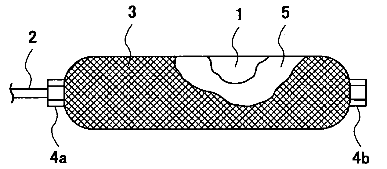
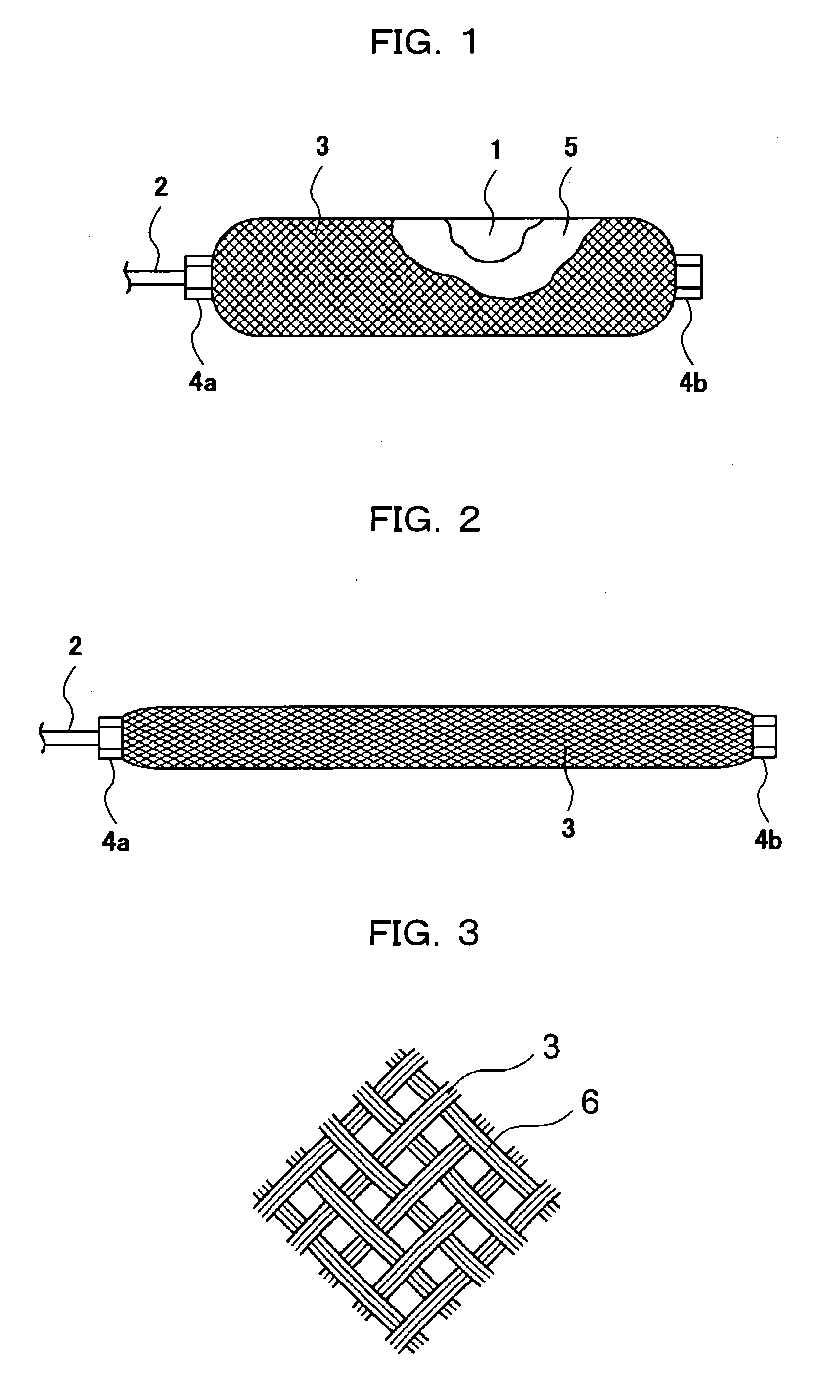
[0044]FIG. 1 is a side view of an air pressure actuator using the air as a fluid in an expanded state according to the invention, and FIG. 2 is a side view of the air pressure actuator of FIG. 1 in a contracted state. In FIG. 1, the mesh sleeve and the low friction member are shown being partly broken away to illustrate the internal structure of the air pressure actuator.

[0045] In FIGS. 1 and 2, a feed / discharge pipe 2 is connected to an end in the lengthwise direction of the of the inner tube 1 which is an expanding / contracting member to feed the air which is a fluid into, or discharge it from, the inner tube 1. The other end of the inner tube 1 is air-tightly closed by inserting a bush (not shown) therein. The inner tube 1 is constituted by using an elastic material such as butyl rubber or the like. An air feeding / discharging device (not shown) constituted by a small air compressor and an electromagnetic valve is connected to the feed / discharge pipe 2.

[0046] The outer periphery o...

second embodiment

[0058] When the air is fed into the actuator in the above embodiment, the inner tube expands in the direction of diameter, producing a tensile stress in the circumferential direction of the inner tube. Therefore, the inner tube swells through the mesh of the mesh sleeve. In the air pressure actuator of the second embodiment, no tensile stress is produced in the circumferential direction of the inner tube when the actuator is operated.

embodiment 2

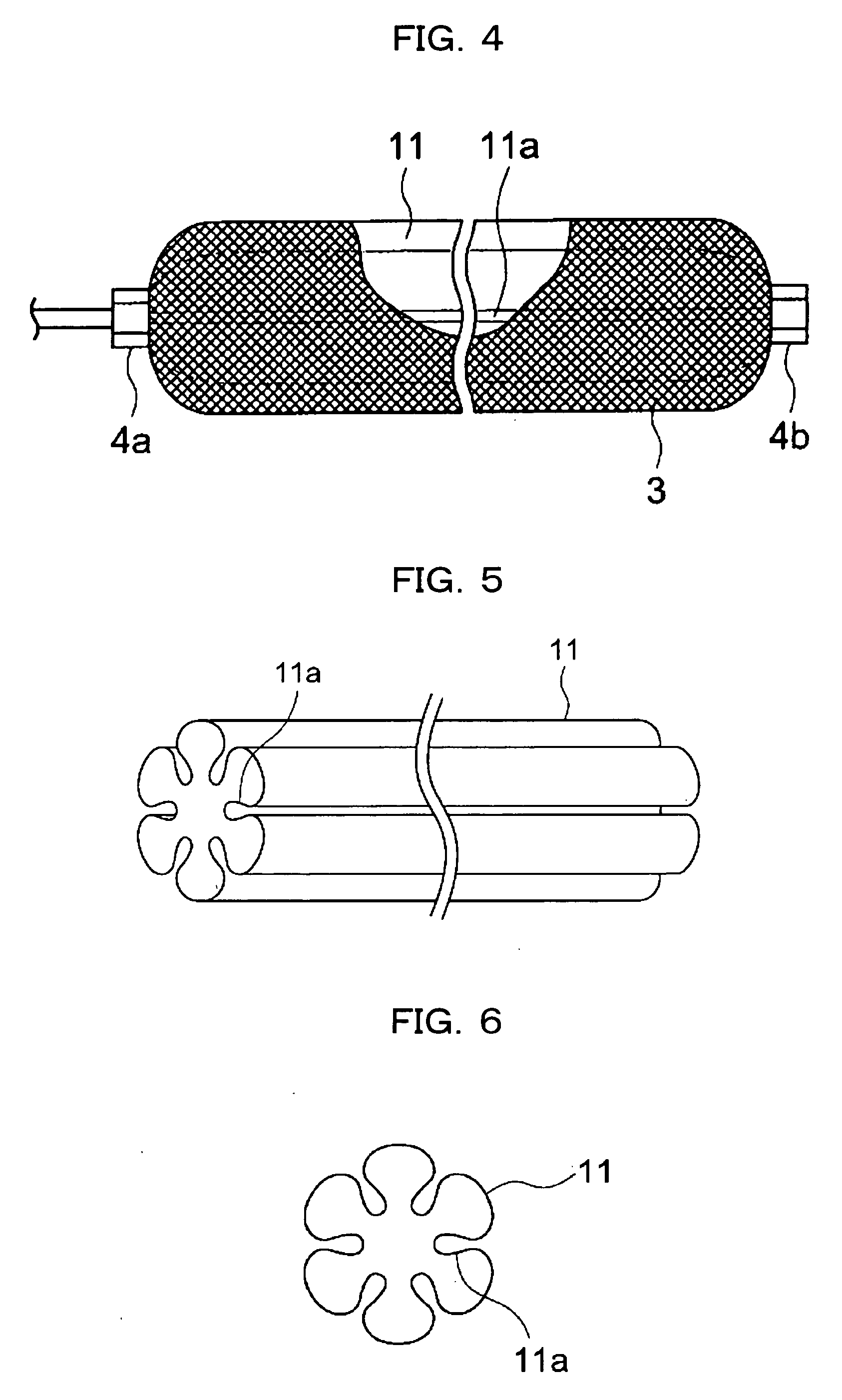
[0059]FIG. 4 is a side view of the air pressure actuator according to the invention, FIG. 5 is a perspective view of the inner tube shown in FIG. 4, FIG. 6 is a transverse sectional view of the inner tube of FIG. 5, and FIG. 7 is a transverse sectional view of the inner tube of FIG. 5 in the expanded state. In FIG. 4, the mesh sleeve is shown being partly broken away to illustrate the inner structure of the actuator.

[0060] In the drawings, the inner tube 11 which is an expanding / contracting member is so constituted that the sectional area of the region surrounded by the tube increases while maintaining the same surface area in a step where it is shifted from the contracted state to the expanded state. That is, the inner tube 11 is provided with a plurality of ridge-like portions 11a that protrude inward at the time of contraction with an equal distance in the circumferential direction of the tube. When the inner tube 11 expands, the ridge-like portions 11a are expanded as shown in F...


PUM


Abstract

A hydraulic pressure actuator having an inner tube and a mesh sleeve covering the outer periphery of the inner tube and longitudinally extendable by pressure fluid fed into the inner tube, wherein a low friction body formed in an elastic cylindrical body by knitting fine fibers is disposed between the inner tube and the mesh sleeve, and the low friction body contributes to an increase in the life of the hydraulic pressure actuator repeatedly performing extension/retraction motions. The hydraulic pressure actuator is used as an actuator for driving a CPM device which supports the extremity of a human body by ay least one of a plurality of members combined with each other and performs the rehabilitation of the joints of a handicapped by operating the member.

Description

TECHNICAL FIELD [0001] The present invention relates to a fluid pressure actuator driven by the feed / discharge of a fluid such as the air and a continuous passive motion (hereinafter abbreviated as CPM) device. BACKGROUND ART [0002] As a fluid pressure actuator, there has been known the one obtained by covering the outer periphery of a rubber tube (inner tube) with a mesh-like covering material (mesh sleeve) made of a resin without expanding / contracting property. The diameter of the mesh sleeve increases when the inner tube is expanded by feeding the air into the inner tube of the fluid pressure actuator. An increase in the diameter of the mesh sleeve is converted into a decrease in the length of the actuator since the material of the mesh sleeve has no expanding / contracting property. A contracting force (driving force) is obtained accompanying the decrease in the length of the actuator. [0003] The fluid pressure actuator constituted chiefly by the elements of the mesh sleeve made o...

Claims


Application Information

Patent Timeline
IPC IPC(8): F01B19/00A61H1/02F15B15/10
CPCA61H1/0237F15B15/103A61H1/0274F15B15/10
Inventor HIRAMATSU, KAZUAKIKONAMI, MAKOTOSATOH, YUTAKAMATSUSHITA, TAISUKESUZUKI, SHIGEKAZUKURODA, KATSUHIROOOKI, KAZUOTODA, AKIBIKO
Owner HITACHI MEDICAL CORP
Why Eureka
Try Eureka