Electrostatic capacity detection type proximity sensor

a technology of electrostatic capacity and proximity sensor, which is applied in the direction of resistance/reactance/impedence, instruments, pulse technique, etc., can solve the problems of detection malfunction, detection is easily affected, and the capacitance to ground of the detection electrode disposed facing the open space is easily affected, so as to achieve the effect of proximity detection with few malfunctions

Active Publication Date: 2006-11-09
CANTECH CO LTD
View PDF9 Cites 113 Cited by
  • Summary
  • Abstract
  • Description
  • Claims
  • Application Information

AI Technical Summary

Benefits of technology

[0012] The present invention was conceived in view of the above problems, and it is an object thereof to provide a capacitance detecting proximity sensor that can form a proximity detection range in a spatially open region, avoid the affects resulting from peripheral objects outside the detection target, and enable proximity detection with few malfunctions.

Problems solved by technology

However, the capacitance to ground of the detection electrode disposed facing the open space is easily affected by the environment or certain peripheral objects outside of the detection target.
When an object forming a large capacitance is present in the vicinity of the proximity sensor, this triggers a detection malfunction even if the object is at a non-proximate position outside of the detection target.
However, this detection is easily affected by the car body and the door and can easily malfunction.
Because the car body and the door form a large capacitance between them and the detection electrode, it is easy for them to be erroneously detected even if they are in a non-proximate position.
Even airborne matter such as raindrops and mist can trigger a detection malfunction.
However, objects that cannot enter this closed space cannot be made to serve as the detection targets.
Optional objects such as human bodies or fixed objects cannot be made to serve as the detection targets.
Moreover, even in the second format, airborne matter such as raindrops and mist can trigger a detection malfunction.
By disposing two detection electrodes on the same surface, the detection range can be formed in a spatially open region in the same manner as in the first format, but in this case the same problems as in the first format arise.
In this manner, although capacitance detecting proximity sensors have the advantages that their principle is simple and they can be configured relatively easily, it is easy for malfunctions resulting from the affects of peripheral objects outside the detection target to arise, and there have been problems in the precision, reliability, and ease-of-use of the detection.

Method used


Image

  • Electrostatic capacity detection type proximity sensor
  • Electrostatic capacity detection type proximity sensor
  • Electrostatic capacity detection type proximity sensor

Examples


Embodiment Construction

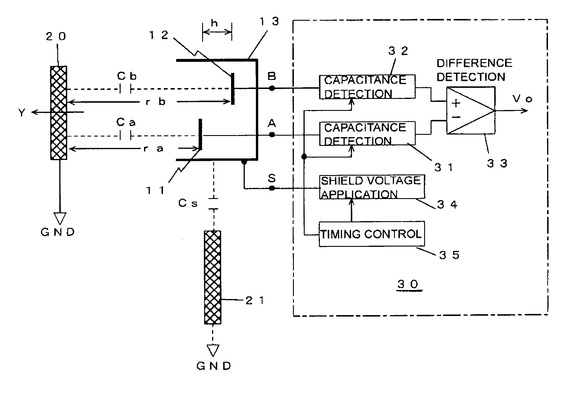
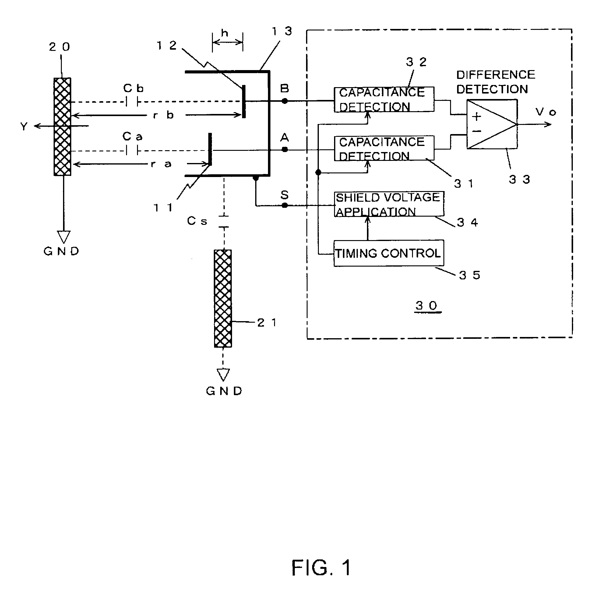
[0039]FIG. 1 is an abbreviated cross-sectional view and block diagram showing the relevant portions of a capacitance detecting proximity sensor pertaining to an embodiment of the present invention. The proximity sensor shown in FIG. 1 is configured using two detection electrodes—a first detection electrode 11 and a second detection electrode 12—and a shield electrode 13. The first detection electrode 11 and the second detection electrode 12 both face a detection direction Y in which a detection subject 20 approaches, and are both disposed so that they have a predetermined range difference h with respect to the detection direction Y.

[0040] The shield electrode 13 surrounds the two detection electrodes 11 and 12 to selectively electrostatically shield the direction (non-detection direction) other than the detection direction Y. Each of the electrodes 11, 12 and 13 is connected to a proximity detection circuit 30. The proximity detection circuit 30 is configured by two capacitance det...


PUM


Abstract

A capacitance detecting proximity sensor forms a proximity detection range in a spatially open region, avoids the effects resulting from peripheral objects outside the detection target, and enables proximity detection with few malfunctions. The proximity sensor includes: a first detection electrode and a second detection electrode that are disposed to have a predetermined range difference h with respect to a detection direction Y in which a detection subject comes into proximity to the proximity sensor and are independent from a ground potential; and a proximity detection circuit that outputs, as a proximity detection output, the difference between a capacitance to ground Ca formed by the first detection electrode and a capacitance to ground Cb formed by the second detection electrode.

Description

TECHNICAL FIELD [0001] The present invention relates to a proximity sensor that detects the proximity of an object by a change in capacitance, and is effectively used in a device for preventing fingers from being pinched in an automatic open / close door attached to a vehicle such as an automobile. BACKGROUND ART [0002] A capacitance detecting proximity sensor detects the proximity of an object (detection subject) such as a human body by measuring the change in capacitance arising due to that object. The principle of such detection is simple and has been known for a long time, but improvements for raising the precision, reliability, and ease-of-use of the detection continue even now, and various configurations have been proposed. The configurations of capacitance detecting proximity sensors can be broadly divided into two formats. [0003] The first format detects / measures, with an appropriate method, the capacitance (capacitance to ground) that one detection electrode disposed facing a...

Claims


Application Information

Patent Timeline
Patent Type & Authority Applications(United States)
IPC IPC(8): G01R27/26H03K17/96
CPCH03K2217/960745H03K17/955G01V3/08H01H36/00
Inventor ABE, HIROSHI
Owner CANTECH CO LTD
Why Eureka
Try Eureka