
Conical dipole antenna and associated methods

a dipole antenna and dipole antenna technology, applied in the field of antennas, can solve the problems of not being able to reduce the size, being obviously unacceptable for use on a vehicle, and antennas, however, are sometimes impractically large for the desired instantaneous bandwidth,

Inactive Publication Date: 2006-11-09
HARRIS CORP
View PDF8 Cites 14 Cited by
  • Summary
  • Abstract
  • Description
  • Claims
  • Application Information

AI Technical Summary

Problems solved by technology

Unfortunately, antennas have not been reduced in size at a comparative level and often are one of the larger components used in a smaller communications device.
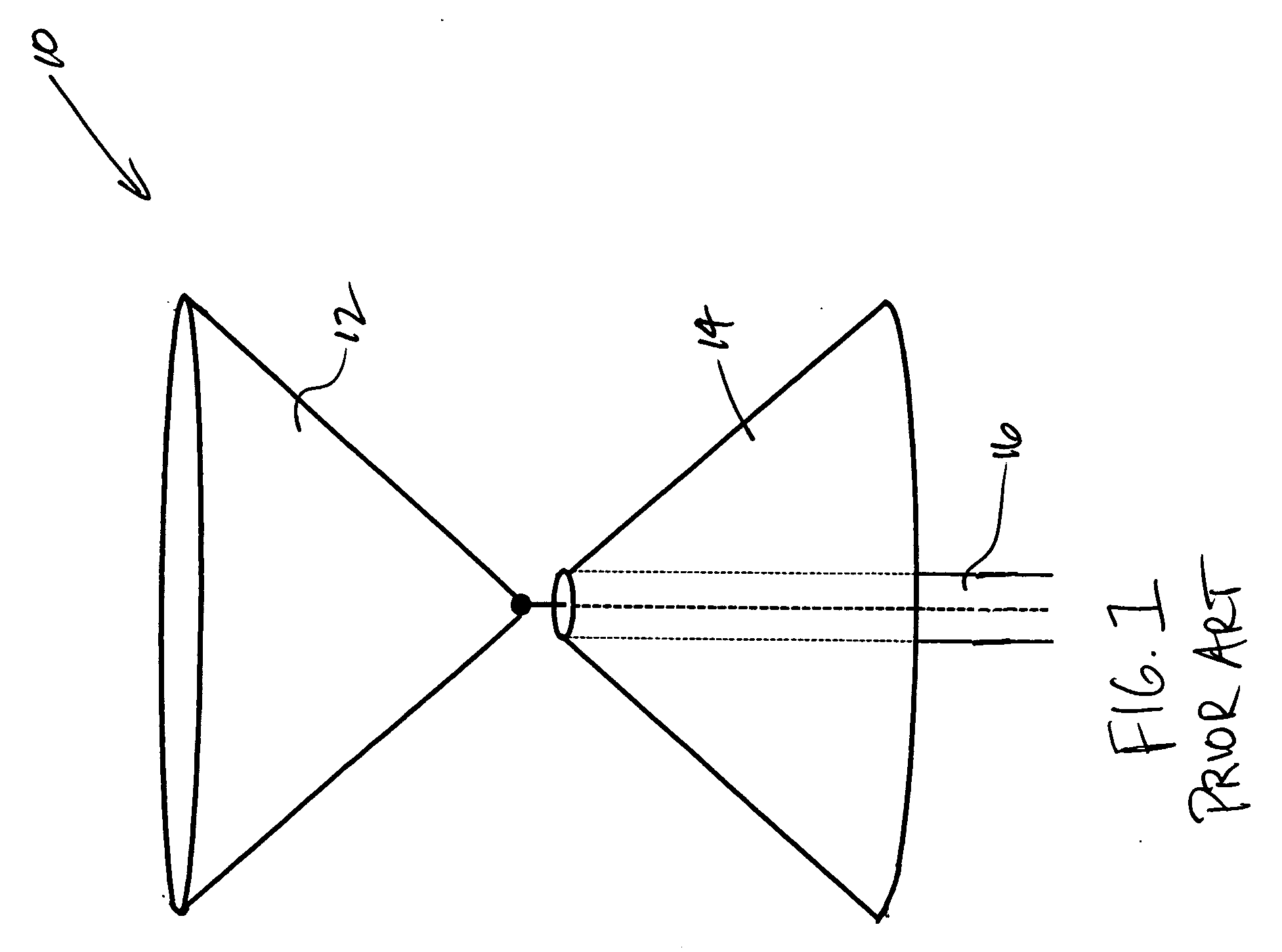
A ¼ wave whip antenna for 5 Mhz is about 50 feet tall, and this is obviously unacceptable for use on a vehicle, and even fixed antennas require wire cage structures.
These antennas, however, are sometimes impractically large for the desired instantaneous bandwidth.
This may be undesirable for various applications.

Method used


Image

  • Conical dipole antenna and associated methods
  • Conical dipole antenna and associated methods
  • Conical dipole antenna and associated methods

Examples


Embodiment Construction

[0019] The present invention will now be described more fully hereinafter with reference to the accompanying drawings, in which preferred embodiments of the invention are shown. This invention may, however, be embodied in many different forms and should not be construed as limited to the embodiments set forth herein. Rather, these embodiments are provided so that this disclosure will be thorough and complete, and will fully convey the scope of the invention to those skilled in the art. Like numbers refer to like elements throughout, and prime notation is used to indicate similar elements in alternative embodiments.

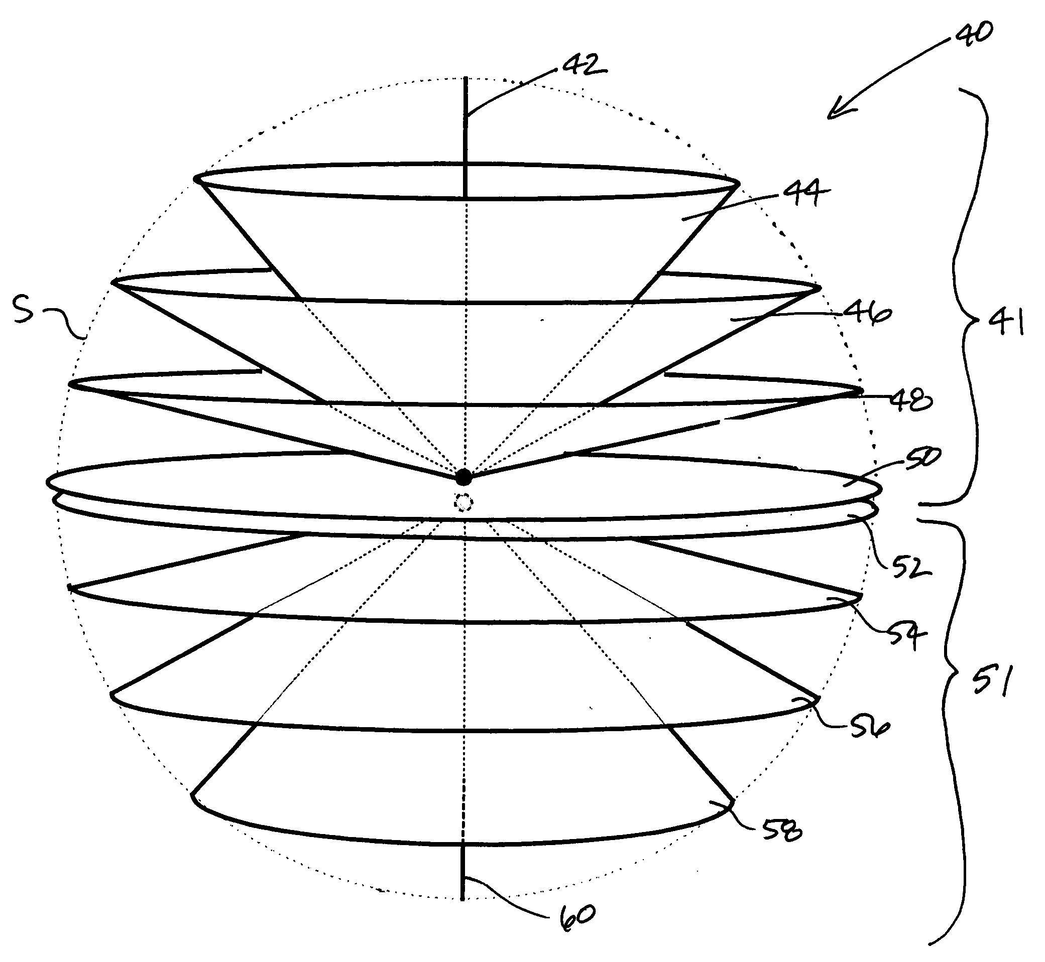
[0020] Referring initially to FIG. 3, a dipole antenna 20 according to a first embodiment of the present invention will now be described. The dipole antenna 20 includes a first antenna element assembly 25 and a second antenna element assembly 21 arranged in a dipole antenna configuration. The first antenna element assembly 25 includes at least one conical antenna element ...


PUM


Abstract

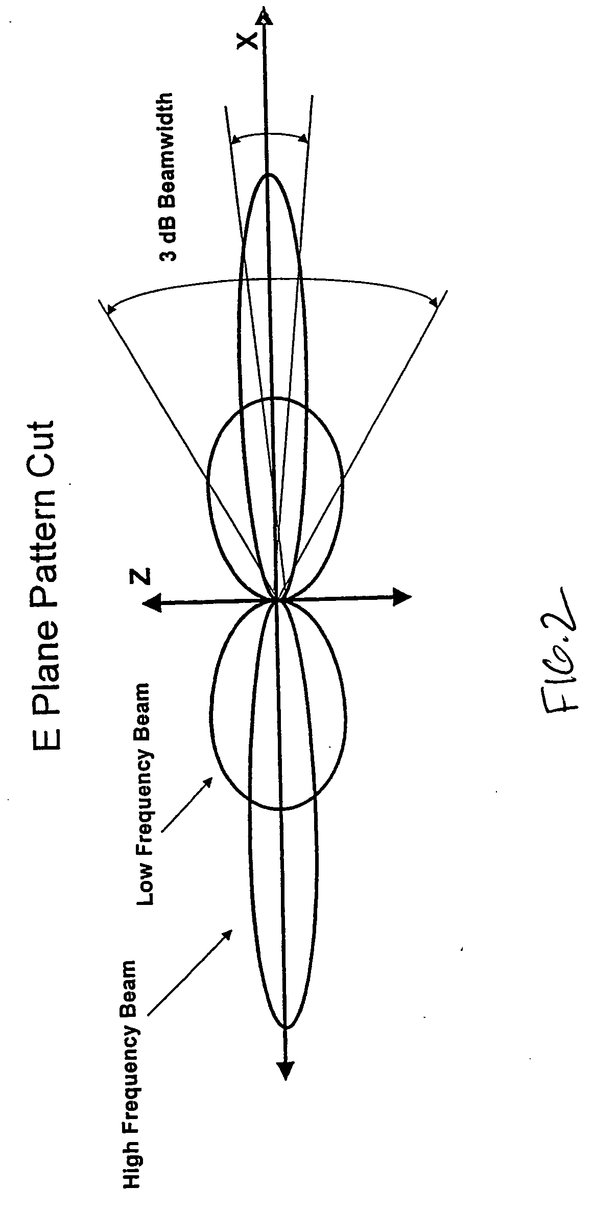
The dipole antenna includes a first antenna element assembly and a second antenna element assembly arranged in a dipole antenna configuration. The first antenna element assembly has one or more conical antenna elements, and the second antenna element assembly has a series of conical antenna elements with each successive conical antenna element at least partially within a prior conical antenna element. Each of the first and second antenna dipole assemblies may also include a respective disk antenna element and a filament antenna element. The antenna has a stable beamwidth and broad bandwidth over a range of frequencies.

Description

FIELD OF THE INVENTION [0001] The present invention relates to the field of antennas, and more particularly, this invention relates to small broadband antennas, and related methods. BACKGROUND OF THE INVENTION [0002] Newer designs and manufacturing techniques have driven electronic components to small dimensions and miniaturized many communication devices and systems. Unfortunately, antennas have not been reduced in size at a comparative level and often are one of the larger components used in a smaller communications device. In those communication applications at below 6 GHz frequencies, the antennas become increasingly larger. In the 3 to 30 Mhz HF region for example, used by military, the proffered antennas become very large relative to operating platforms. A ¼ wave whip antenna for 5 Mhz is about 50 feet tall, and this is obviously unacceptable for use on a vehicle, and even fixed antennas require wire cage structures. It becomes increasingly important in these communication app...

Claims


Application Information

Patent Timeline
IPC IPC(8): H01Q13/00
CPCH01Q9/28H01Q5/40H01Q21/0056
Inventor PARSCHE, FRANCIS EUGENE
Owner HARRIS CORP
Learn More