Tag-use antenna and tag using the same

a technology of tag-use antenna and tag, which is applied in the direction of resonant antenna, radiating element structure, instruments, etc., can solve the problems of hampered practice and faced with practical problems

Active Publication Date: 2007-11-01
FUJITSU LTD
View PDF10 Cites 83 Cited by
  • Summary
  • Abstract
  • Description
  • Claims
  • Application Information

AI Technical Summary

Benefits of technology

[0041]The present invention is contrived to enable a provision of an extremely compact, tag-use antenna of which a communication distance is changed little by

Problems solved by technology

As such, a practicality is hampered if a communication distance of the antenna fluctuates when being attached onto various kinds of bodies, that is, when the operating frequency is

Method used


Image

  • Tag-use antenna and tag using the same
  • Tag-use antenna and tag using the same
  • Tag-use antenna and tag using the same

Examples


Embodiment Construction

[0050]The following is a detailed description of the preferred embodiment of the present invention by referring to the accompanying drawings.

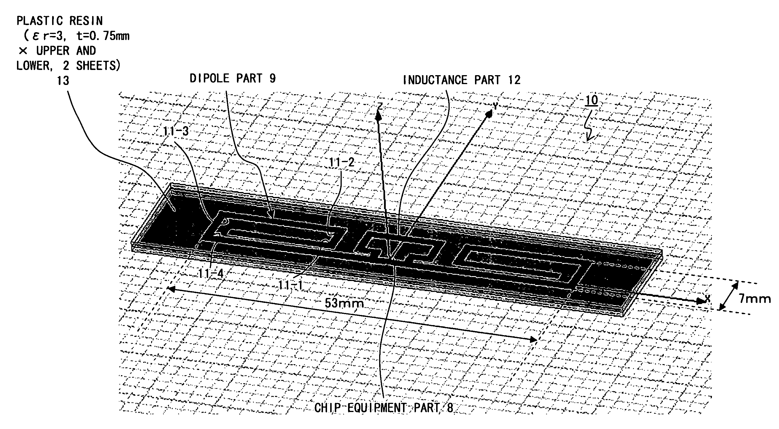
[0051]FIG. 4 is a diagonal view diagram showing a configuration of an extremely compact tag-use antenna according to an embodiment. Note that FIG. 4 shows a tag-use antenna along with a tag built in with the tag-use antenna. The tag is configured by sandwiching the both sides of the tag-use antenna by a plastic resin or paper. FIG. 4 indicates a tag-use antenna internally by perspectively showing the plastic or paper tag.

[0052]The entire size of the tag-use antenna 10 shown in FIG. 4 is 53 mm horizontal by 7 mm vertical.

[0053]The tag-use antenna 10 comprises a dipole antenna, a feed part and an inductance part which are featured by a conductor within the same plane. The conductor preferably uses copper, silver or aluminum.

[0054]The feed part is formed to enable an equipment of an LSI chip at the center of the dipole antenna and comprises a chip...


PUM


Abstract

The present invention relates to a tag-use antenna allowing a miniaturization while maintaining a constant minimal change of a communication distance. The tag-use antenna has a feed part of a folded dipole antenna of a size of 53 mm long and 7 mm wide being connected to, and equipped with, an LSI chip of Rc=500 ohms and Cc=1.4 pF and is covered with plastic resin 13 of the dielectric constant εr=3 and thickness of t=0.75 mm on both sides of the antenna. The dipole part of 1 mm wire path width of the tag-use antenna is formed in a rectangular spiral by being bent inward from both ends at bending parts at four places. The entire length of the dipole antenna when extending the four bending parts straight is featured so as to be shorter than one half of a resonance wavelength of the antenna. An inductance part is featured in the intermediate part of the both dipole parts in the neighborhood of the center of the antenna. The inductance part is connected to the chip equipment part in parallel with the both dipole parts.

Description

BACKGROUND OF THE INVENTION[0001]1. Field of the Invention[0002]The present invention relates to an ultra-miniature, tag-use antenna used for a large-scale integration (LSI) chip and a tag using it for use in a radio frequency identification (RFID) system which is capable of carrying out a communication between a reader / writer and a tag by using a radio high frequency signal.[0003]2. Description of the Related Art[0004]An RFID system is one for transmitting a signal of approximately one watt from a reader / writer (simply “RW” hereinafter), receiving the signal on a tag side and retransmitting a response signal back to the RW side, by using an ultra high frequency (UHF) between 860 MHz and 960 MHz, thereby enabling the RW to read information stored in the tag.[0005]The tag is constituted by a tag-use metallic antenna formed on a flat surface such as a sheet or a film, et cetera, of approximately 0.1 mm thick, and an LSI chip connected to a feed point of the tag-use antenna. The LSI ch...

Claims


Application Information

Patent Timeline
IPC IPC(8): H01Q9/26
CPCG06K19/07749H01Q9/16H01Q1/38H01Q1/2216
Inventor KAI, MANABUMANIWA, TORUYAMAGAJO, TAKASHI
Owner FUJITSU LTD
Why Eureka
Try Eureka