Portable wireless machine

a wireless machine and portable technology, applied in the direction of resonant antennas, elongated active element feeds, differential interacting antenna combinations, etc., can solve the problems of undesirable differences in antenna gain, possible sometimes undesirable deterioration of antenna gain, so as to reduce the thickness of portable radio devices

Inactive Publication Date: 2005-10-27
PANASONIC CORP
View PDF19 Cites 86 Cited by
  • Summary
  • Abstract
  • Description
  • Claims
  • Application Information

AI Technical Summary

Benefits of technology

[0057] According to this structure, since the electric conductive frame forming a part of the upper casing is used as the antenna element, the thickness of the portable radio device can be decreased.

Problems solved by technology

However, since the direction of a main polarized wave emitted from the antenna is limited to a specific direction, a difference is undesirably generated in the antenna gain between a case that the portable telephone is held by a left hand during speaking (a left hand speaking state) and a case that the portable telephone is held by a right hand (a right hand speaking state).
Further, in the hinge portion contained antenna, under a state in which the portable telephone is allowed to come near to the ear and the mouth to speak (refer this state as to a speaking state, hereinafter), when the hinge portion is held by a hand, the antenna gain may be sometimes undesirably deteriorated, because the antenna portion is covered with the hand.
Further, in the flip part contained antenna, while the flip part is closed, a portable telephone main body is allowed to come near to the antenna portion so that the antenna gain may be possibly deteriorated.
Still further, in the plurality of element contained antenna, while the upper and lower casings are opened to speak, when a part near the radiation element is covered with a hand, the antenna gain may be undesirably deteriorated.

Method used


Image

  • Portable wireless machine
  • Portable wireless machine
  • Portable wireless machine

Examples


first embodiment

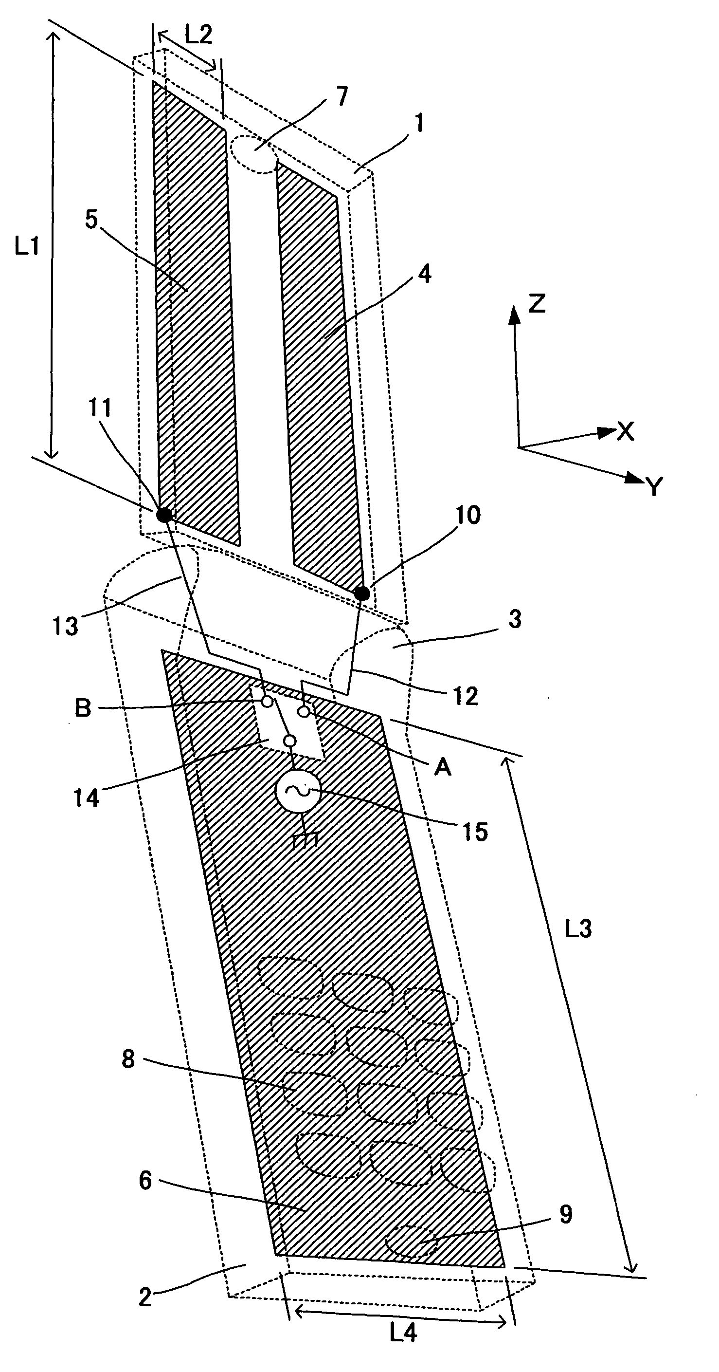
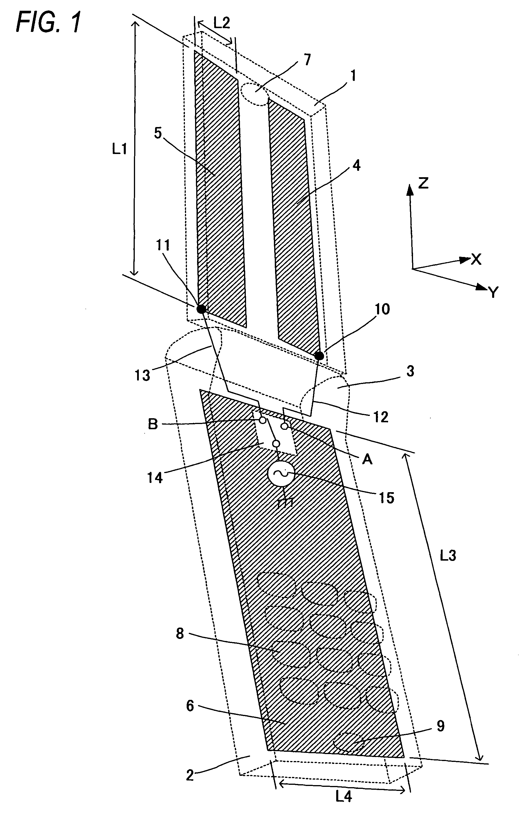
[0096]FIG. 1 is a schematic structural diagram of a portable radio device in a first embodiment of the present invention. The portable radio device in this embodiment is a portable radio device having a foldable structure and is shown in an opened state (refer this state as to an opening state, hereinafter) in FIG. 1. The portable radio device includes an upper case 1, a lower case 2, a hinge portion 3, a plate shaped conductor 4, a plate shaped conductor 5, a ground plate 6, a speaker 7, an operating key 8 and a microphone 9.

[0097] The upper case 1 and the lower case 2 as one example of a first casing and a second casing are formed with a resin as an insulator and ordinarily set to the length of about 10 mm and the width of about 50 mm. The upper case 1 and the lower case 2 are respectively connected in the hinge portion 3 so as to freely rotate. Thus; a foldable or a collapsible structure is formed.

[0098] In the upper end part of the upper case 1, the speaker 7 is disposed. In t...

second embodiment

[0120]FIG. 5 is a schematic structural diagram of a portable radio device in a second embodiment of the present invention. The portable radio device in this embodiment is also a portable radio device having a foldable or collapsible structure. In FIG. 5, an opened state (refer this state to as an opening state, hereinafter) is shown. In FIG. 5, duplicated portions of FIG. 1 are designated by the same reference numerals.

[0121] In the portable radio device shown in FIG. 5, the plate shaped conductor 4 or the plate shaped conductor 5 that is not selected is grounded in a ground plate 6.

[0122] In FIG. 5, feeders 12 and 13 are respectively connected to high frequency switches 24 and 25. The high frequency switch 24 performs an operation for switching whether an electric signal of the feeder 12 is transmitted to a feeding portion 15 or grounded to the ground plate 6. Further, the high frequency switch 25 performs an operation for switching whether an electric signal of the feeder 13 is ...

third embodiment

[0128]FIG. 7 is a schematic structural diagram of a portable radio device according to a third embodiment of the present invention. The portable radio device in this embodiment is also a portable radio device having a foldable or collapsible structure. In FIG. 7, an opened state (refer this state to as an opening state, hereinafter) is shown. In FIG. 7, the duplicated portions of FIG. 1 are designated by the same reference numerals.

[0129] In FIG. 7, a helical element 30 is inserted between a plate shaped conductor 5 and a high frequency switch 31.

[0130] In FIG. 7, the helical element 30 is formed by winding a conductor in a coil shape. The electric length thereof is preferably set to substantially half-wavelength in an operating frequency (for instance, 900 MHz). In this case, the helical element 30 is inserted between the plate shaped conductor 5 and the high frequency switch 31, so that a phase for exciting the plate shaped conductor 5 is inverted.

[0131]FIGS. 8 and 9 are side v...


PUM


Abstract

An upper case (1) is connected to a lower case (2) in a hinge portion (3) so as to freely rotate. A plate shaped conductor (4) and a plate shaped conductor (5) are disposed along the surface of the case in the upper case (1). A ground plate (6) is formed in a ground pattern of a circuit board disposed in the lower case (2). The plate shaped conductor (4) and the plate shaped conductor (5) are selected by a high frequency switch (14) and connected to one end of a feeding portion (15). The other end of the feeding portion (15) is connected to the ground plate (6) to form a dipole antenna.

Description

TECHNICAL FIELD [0001] The present invention relates to a portable radio device such as a portable telephone, and more particularly to a portable radio device having a collapsible casing. BACKGROUND ART [0002] A portable radio device with a collapsible structure ordinarily has a mechanism including an upper casing and a lower casing connected by a hinge so as to be freely open and close. Thus, the portable radio device can take an opening state and a closing state. The portable radio device has two advantages of a high visibility and an easy portability that a viewable display screen can be enlarged under a state that the device is opened and used (namely, an opening state) and the device can be made compact under a state that the device is closed and used (a closing state) from the viewpoint of such structural characteristics. [0003] As an antenna of a foldable portable telephone, a protrusion type antenna disposed in a casing is disclosed in JP-A-2001-45123. [0004] For such a prot...

Claims


Application Information

Patent Timeline
Patent Type & Authority Applications(United States)
IPC IPC(8): H01Q1/24H01Q3/24H01Q9/16H01Q9/28H01Q9/30H01Q9/42H01Q21/29H01Q23/00H04M1/00H04M1/02
CPCH01Q1/243H01Q3/24H01Q3/247H01Q9/16H04M1/0214H01Q9/42H01Q21/29H01Q23/00H01Q9/285
Inventor SAITOU, YUTAKAKOYANAGI, YOSHIOYAMADA, KENICHIKOSHI, MASASHIYAMAZAKI, YUKARI
Owner PANASONIC CORP
Why Eureka
Try Eureka