Encoder apparatus and decoder apparatus

Active Publication Date: 2006-11-09
PANASONIC INTELLECTUAL PROPERTY CORP OF AMERICA
View PDF11 Cites 44 Cited by
  • Summary
  • Abstract
  • Description
  • Claims
  • Application Information

AI Technical Summary

Benefits of technology

[0019] The present invention is capable of performing coding of a spectrum at a low bit rate and with high quality without any collapse of a harmonic structure of the spectrum. Furthermore, the present invention is also capable of improving sound quality when decoding this coded signal.

Problems solved by technology

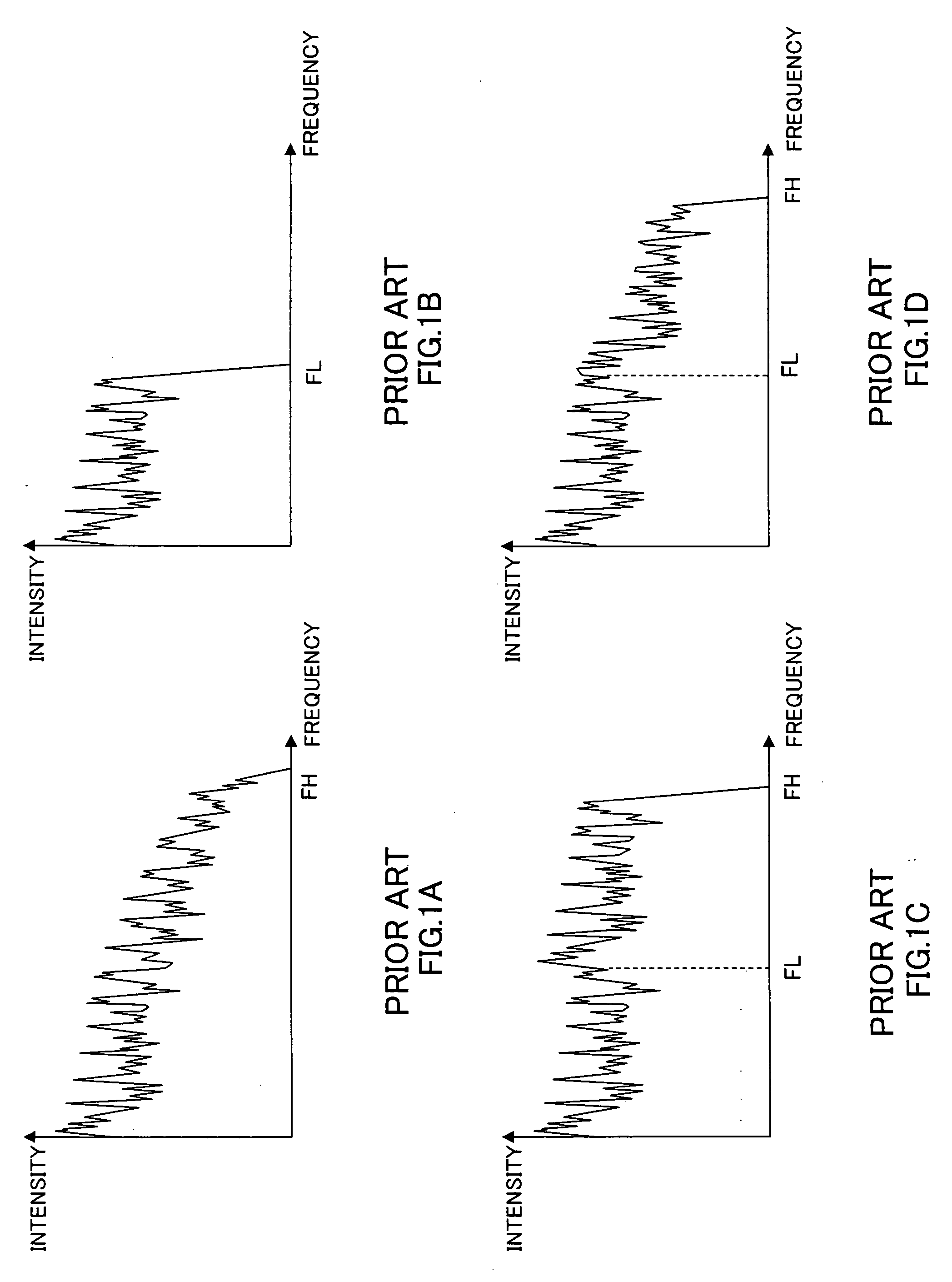
However, since such a narrow band signal is so narrow that its frequency band is a maximum of 3.4 kHz, the quality thereof is such that it gives the user an impression that a sound is muffled, which results in a problem that it lacks a sense of realism.
However, when the signal to be coded is voice, although a wideband signal has relatively high quality, it is not sufficient when an audio signal is the target or a voice signal of higher quality with a sense of realism is required.
However, these audio coding schemes have a wide frequency band of a signal to be coded, which results in a problem that the bit rate of a coded signal increases.

Method used


Image

  • Encoder apparatus and decoder apparatus
  • Encoder apparatus and decoder apparatus
  • Encoder apparatus and decoder apparatus

Examples


embodiment 1

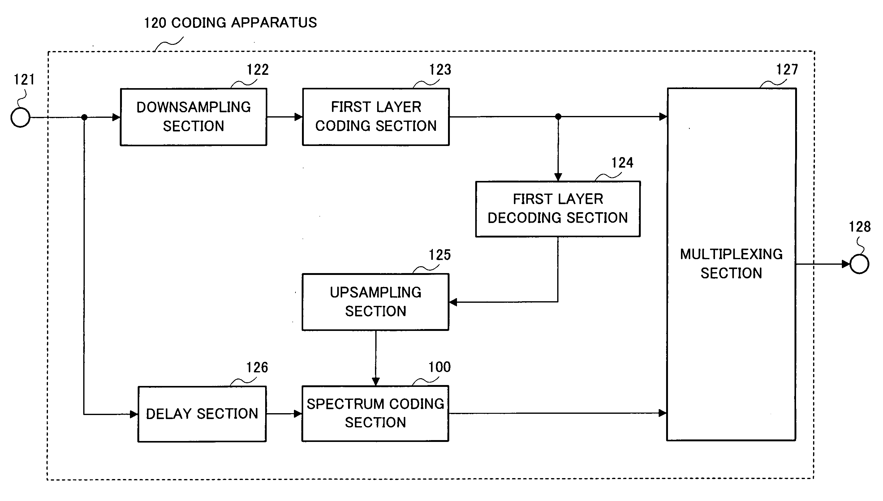
[0043]FIG. 3 is a block diagram showing the principal configuration of radio transmission apparatus 130 when a radio coding apparatus according to Embodiment 1 of the present invention is mounted on the transmitting side of a radio communication system.

[0044] This radio transmission apparatus 130 includes coding apparatus 120, input apparatus 131, A / D conversion apparatus 132, RF modulation apparatus 133 and antenna 134.

[0045] Input apparatus 131 converts sound wave W11 audible to human ears to an analog signal which is an electric signal and outputs the signal to A / D conversion apparatus 132. A / D conversion apparatus 132 converts this analog signal to a digital signal and outputs the digital signal to coding apparatus 120. Coding apparatus 120 encodes the input digital signal, generates a coded signal and outputs the coded signal to RF modulation apparatus 133. RF modulation apparatus 133 modulates the coded signal, generates a modulated coded signal and outputs the modulated cod...

embodiment 2

[0112]FIG. 15 is a block diagram showing the principal configuration of spectrum coding section 200 in a coding apparatus according to Embodiment 2 of the present invention. This spectrum coding section 200 has a basic configuration similar to that of spectrum coding section 100 shown in FIG. 5 and the same components are assigned the same reference numerals and explanations thereof will be omitted.

[0113] A feature of this embodiment is to make a filter function used in the filtering section simpler than that in Embodiment 1.

[0114] For the filter function used in filtering section 201, a simplified one as shown in the following equation is used. P⁡(z)=11-z-T(Equation⁢ ⁢5)

This equation corresponds to a filter function assuming M=0, β0=1 in (Equation 1).

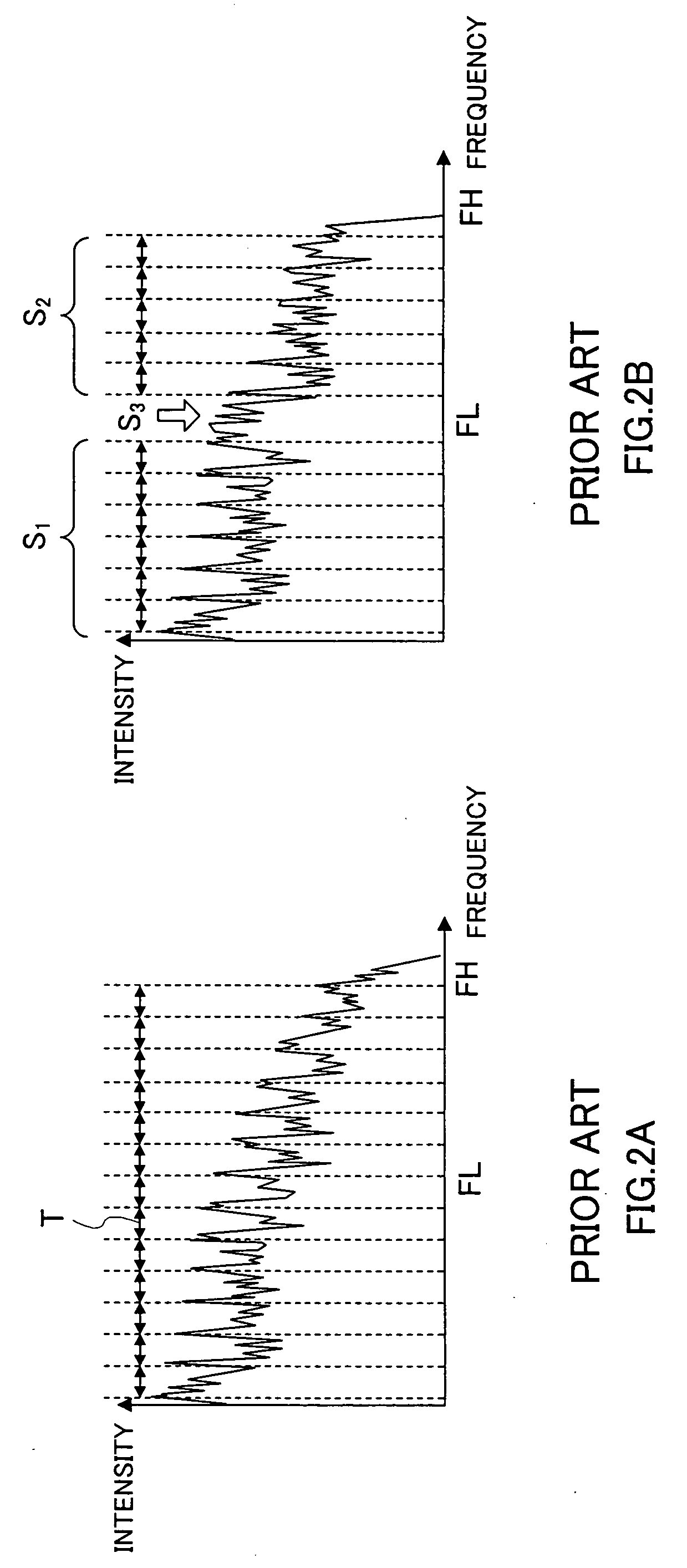
[0115]FIG. 16 illustrates an overview of filtering using the above described filter.

[0116] Estimated value S′2(k) of a second spectrum is obtained by sequentially copying low-frequency spectra separated by T. Furthermore, search ...

embodiment 3

[0121]FIG. 17 is a block diagram showing the principal configuration of spectrum coding section 300 in a coding apparatus according to Embodiment 3 of the present invention. This spectrum coding section 300 has a basic configuration similar to that of spectrum coding section 100 shown in FIG. 5 and the same components are assigned the same reference numerals and explanations thereof will be omitted.

[0122] A feature of this embodiment is to further comprise outline calculation section 301 and multiplexing section 302 and perform coding of envelope information about a second spectrum after estimating the second spectrum.

[0123] Search section 108 outputs optimum pitch coefficient T′ to multiplexing section 302 and outputs estimated value S′2(k) of the second spectrum generated using this pitch coefficient T′ to outline calculation section 301. Outline calculation section 301 calculates envelope information about second spectrum S2(k) based on second spectrum S2(k) provided from frequ...


PUM


Abstract

A coding apparatus capable of coding a spectrum at a low bit rate and with high quality without producing any disturbance in a harmonic structure of the spectrum. In this apparatus, internal state setting section (106) sets an internal state of filtering section (107) using first spectrum S1(k). Pitch coefficient setting section (109) outputs pitch coefficient T by gradually changing it. Filtering section (107) calculates estimated value S′2(k) of second spectrum S2(k) based on pitch coefficient T. Search section (108) calculates the degree of similarity between S2(k) and S′2(k). At this time, pitch coefficient T′ corresponding to the maximum calculated degree of similarity is given to filter coefficient calculation section (110). Filter coefficient calculation section (110) determines filter coefficient βi using this pitch coefficient T′.

Description

TECHNICAL FIELD [0001] The present invention relates to a coding apparatus mounted on a radio communication apparatus or the like for coding a voice signal, audio signal or the like and a decoding apparatus for decoding this coded signal. BACKGROUND ART [0002] A coding technology for compressing a voice signal, audio signal or the like to a low bit rate signal is particularly important from the standpoint of effectively using a transmission path capacity (channel capacity) of radio waves or the like and a recording medium in a mobile communication system. [0003] Examples of a voice coding scheme for coding a voice signal include schemes like G726, G729 standardized by the ITU-T (International Telecommunication Union Telecommunication Standardization Sector). These schemes use narrow band signals (300 Hz to 3.4 kHz) as coding targets and can perform high quality coding at bit rates of 8 kbits / s to 32 kbits / s. However, since such a narrow band signal is so narrow that its frequency ba...

Claims


Application Information

Patent Timeline
IPC IPC(8): H04B14/04
CPCH04B1/667G10L19/083
Inventor OSHIKIRI, MASAHIRO
Owner PANASONIC INTELLECTUAL PROPERTY CORP OF AMERICA
Why Eureka
Try Eureka