Sound encoding apparatus and sound encoding method

Active Publication Date: 2005-11-17
PANASONIC INTELLECTUAL PROPERTY CORP OF AMERICA
View PDF18 Cites 43 Cited by
  • Summary
  • Abstract
  • Description
  • Claims
  • Application Information

AI Technical Summary

Benefits of technology

[0019] It is an object of the present invention to provide an acoustic coding apparatus and acoustic coding method capable of performing coding on even a signal which consists predominantly of speech with music and noise superimposed in the background, with a short delay, at a low bit rate and with high quality.
[0020] This object can be attained by performing coding on an enhancement layer with the time length of enhancement layer frames set to be shorter than the time length of base layer frames and performing coding on a signal which consists predominantly of speech with music and noise superimposed in the background, with a short delay, at a low bit rate and with high quality.

Problems solved by technology

However, when a signal which consists predominantly of a speech signal with music and environmental sound superimposed in the background is encoded, applying a speech coding involves a problem that not only the signal in the background but also the speech signal deteriorates due to the influence of music and environmental sound in the background, degrading the overall quality.
This is a problem caused by the fact that the speech coding is based on a method specialized for the speech model of the CELP.
Furthermore, there is another problem that the signal band to which the speech coding is applicable is up to 7 kHz at most and signals having higher frequencies cannot be covered for structural reasons.
On the other hand, to realize high quality coding, it is necessary to use signals at a high bit rate and the problem is that if the bit rate is mitigated to as low as approximately 32 kbit / s, the quality of the decoded signal degrades drastically.
This results in a problem that the method cannot be used for a communication network having a low transmission bit rate.
However, such scalable coding has a problem that delays in the enhancement layer increase.
Such an increase of delay constitutes a serious problem in realizing a speech communication service.
As shown above, the conventional apparatus has a problem that it is difficult to perform coding on a signal which consists predominantly of speech with music and noise superimposed in the background, with a short delay, at a low bit rate and with high quality.

Method used


Image

  • Sound encoding apparatus and sound encoding method
  • Sound encoding apparatus and sound encoding method
  • Sound encoding apparatus and sound encoding method

Examples


embodiment 1

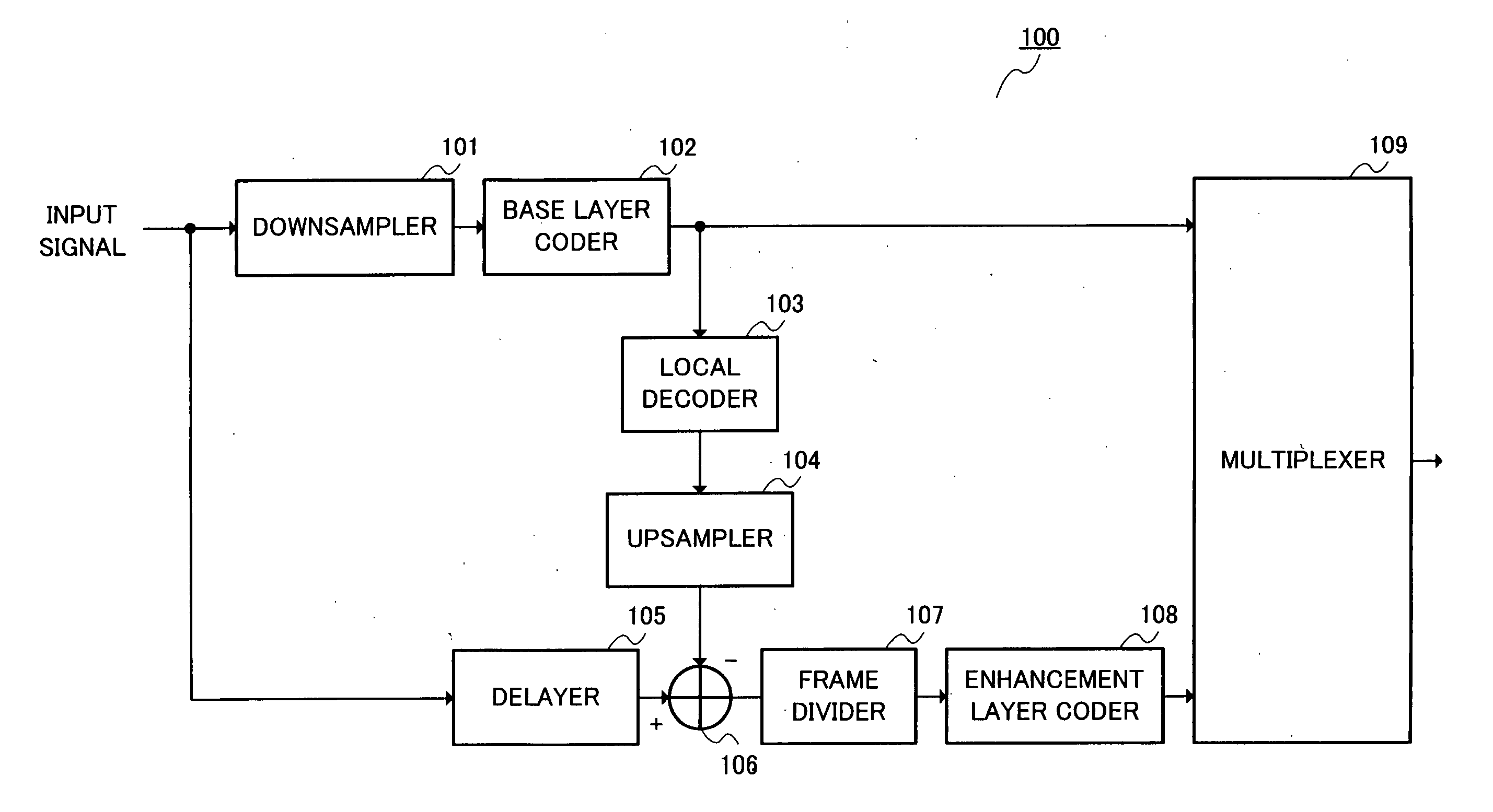
[0052]FIG. 3 is a block diagram showing the configuration of an acoustic coding apparatus according to Embodiment 1 of the present invention. An acoustic coding apparatus 100 in FIG. 3 is mainly constructed of a downsampler 101, a base layer coder 102, a local decoder 103, an upsampler 104, a delayer 105, a subtractor 106, a frame divider 107, an enhancement layer coder 108 and a multiplexer 109.

[0053] In FIG. 3, the downsampler 101 receives input data (acoustic data) of a sampling rate 2*FH, converts this input data to a sampling rate 2*FL which is lower than the sampling rate 2*FH and outputs the input data to the base layer coder 102.

[0054] The base layer coder 102 encodes the input data of the sampling rate 2*FL in units of a predetermined base frame and outputs a first coded code which is the coded input data to the local decoder 103 and multiplexer 109. For example, the base layer coder 102 encodes the input data according to a CELP coding.

[0055] The local decoder 103 decod...

embodiment 2

[0083] This embodiment will describe an example where CELP coding is used for coding of the base layer. FIG. 9 is a block diagram showing an example of the internal configuration of a base layer coder according to Embodiment 2 of the present invention. FIG. 9 shows the internal configuration of the base layer coder 102 in FIG. 3. The base layer coder 102 in FIG. 9 is mainly constructed of an LPC analyzer 701, a perceptual weighting section 702, an adaptive codebook searcher 703, an adaptive vector gain quantizer 704, a target vector generator 705, a noise codebook searcher 706, a noise vector gain quantizer 707 and a multiplexer 708.

[0084] The LPC analyzer 701 calculates LPC coefficients of an input signal of a sampling rate 2*FL and converts these LPC coefficients to a parameter set suitable for quantization such as LSP coefficients and quantizes the parameter set. Then, the LPC analyzer 701 outputs the coded code obtained by this quantization to the multiplexer 708.

[0085] Furthe...

embodiment 3

[0102] This embodiment is characterized by the use of transform coding whereby an input signal of the enhancement layer is transformed into a coefficient of the frequency domain and then the transformed coefficients are encoded. The basic configuration of an enhancement layer coder 108 according to this embodiment will be explained using FIG. 12. FIG. 12 is a block diagram showing an example of the internal configuration of an enhancement layer coder according to Embodiment 3 of the present invention. FIG. 12 shows an example of the internal configuration of the enhancement layer coder 108 in FIG. 3. The enhancement layer coder 108 in FIG. 12 is mainly constructed of an MDCT section 1001 and a quantizer 1002.

[0103] The MDCT section 1001 MDCT-transforms (modified discrete cosine transform) an input signal output from the frame divider 107 to obtain MDCT coefficients. An MDCT transform completely overlaps successive analysis frames by half the analysis frame length. And the orthogona...


PUM


Abstract

A downsampler 101 converts input data having a sampling rate 2*FH to a sampling rate 2*FL which is lower than the sampling rate 2*FH. A base layer coder 102 encodes the input data having the sampling rate 2*FL in predetermined base frame units. A local decoder 103 decodes a first coded code. An upsampler 104 increases the sampling rate of the decoded signal to 2*FH. A subtractor 106 subtracts the decoded signal from the input signal and regards the subtraction result as a residual signal. A frame divider 107 divides the residual signal into enhancement frames having a shorter time length than that of the base frame. An enhancement layer coder 108 encodes the residual signal divided into the enhancement frames and outputs a second coded code obtained by this coding to a multiplexer 109.

Description

TECHNICAL FIELD [0001] The present invention relates to an acoustic coding apparatus and acoustic coding method which compresses and encodes an acoustic signal such as a music signal or speech signal with a high degree of efficiency, and more particularly, to an acoustic coding apparatus and acoustic coding method which carries out scalable coding capable of even decoding music and speech from part of a coded code. BACKGROUND ART [0002] An acoustic coding technology which compresses a music signal or speech signal at a lowbit rate is important for effective utilization of a transmission path capacity of radio wave, etc., in a mobile communication and a recording medium. As speech coding methods for coding a speech signal, there are methods like G726, G729 which are standardized by the ITU (International Telecommunication Union). These methods can perform coding on a narrowband signal (300 Hz to 3.4 kHz) at a bit rate of 8 kbit / s to 32 kbit / s with high quality. [0003] Furthermore, th...

Claims


Application Information

Patent Timeline
IPC IPC(8): G10L19/12G10L19/02G10L21/0388G10L25/90
CPCG10L19/16G10L19/24G10L19/22
Inventor OSHIKIRI, MASAHIRO
Owner PANASONIC INTELLECTUAL PROPERTY CORP OF AMERICA
Why Eureka
Try Eureka