Method and apparatus for reporting inter-frequency measurement using RACH message in a mobile communication system
a mobile communication system and inter-frequency measurement technology, applied in the field of mobile communication systems, can solve the problems of excessive increase in the uplink load, and achieve the effect of reducing the signaling overhead of the rach messag
- Summary
- Abstract
- Description
- Claims
- Application Information
AI Technical Summary
Benefits of technology
Problems solved by technology
Method used
Image
Examples
first embodiment
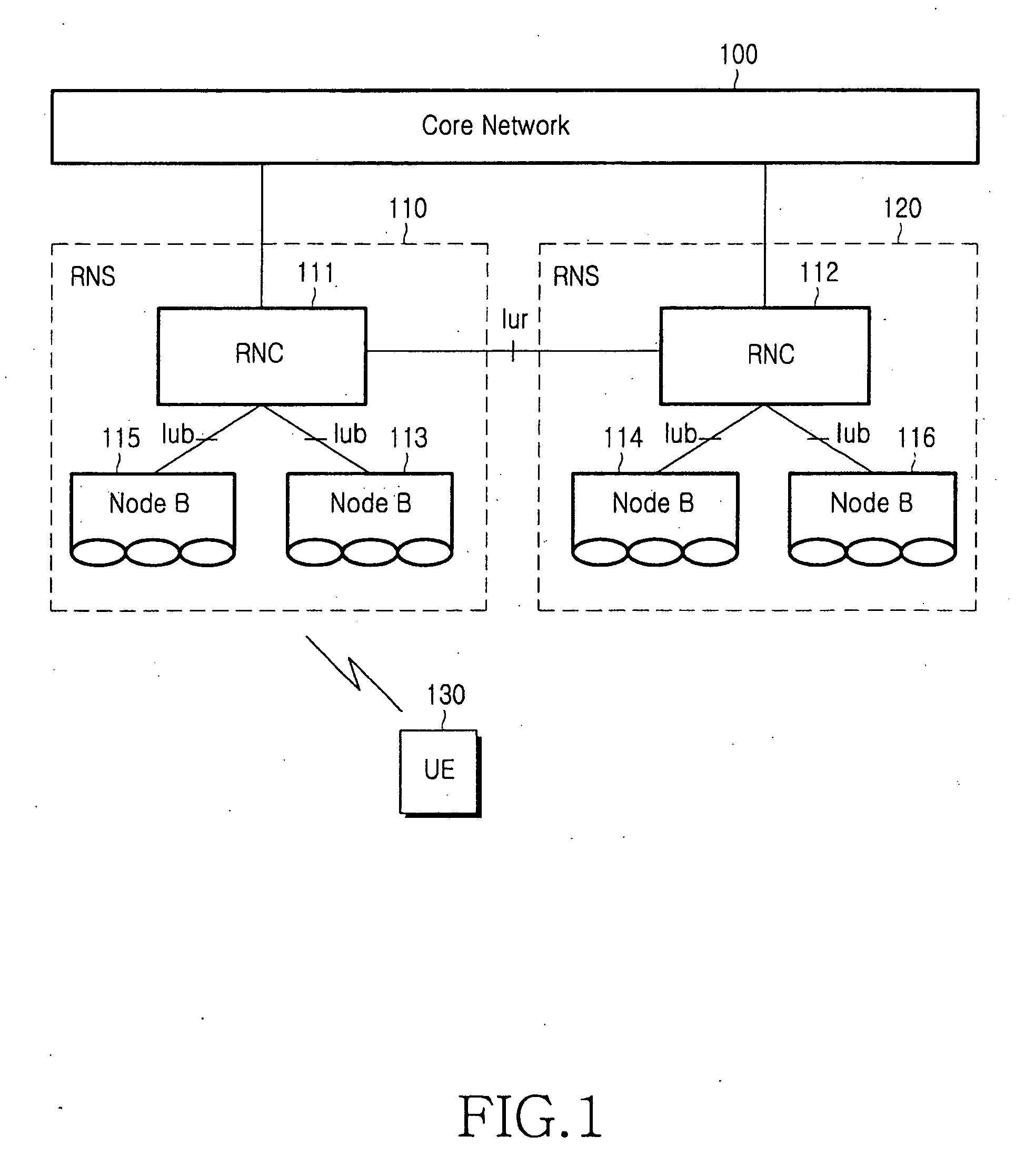
[0086]FIG. 7 is a message flow diagram for illustrating exemplary signaling between an SRNC and a CRNC according to the present invention. Herein, a UE is located in a cell controlled by a CRNC and communicates with a CN via an SRNC. Then, there is an Iur interface between the SRNC and the CRNC.
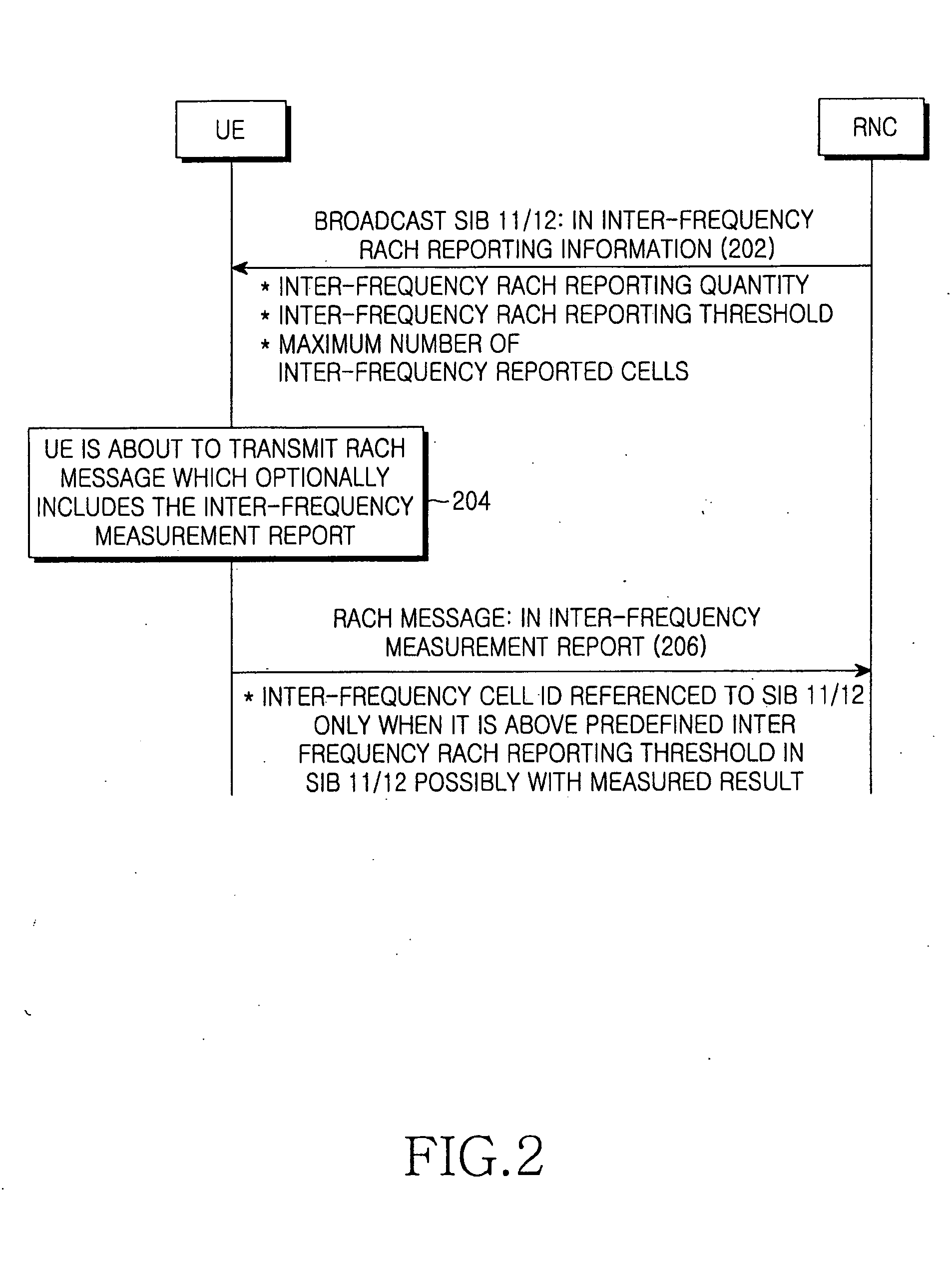
[0087] As illustrated inFIG. 7, in step 702, a UE sets, in a Cell Update message, measurement results for the cells of the non-used frequencies having radio strength higher than a ‘threshold referred to SIB11 / 12’ as an inter-frequency cell IDs based on an inter-frequency cell info list in the SIB11 / 12, and transmits the Cell Update message to a CRNC. In step 704, the CRNC forwards the Cell Update message to an SRNC along with an uplink (UL) signaling transfer message. At this moment, the CRNC converts the inter-frequency cell IDs into cell information of the cell corresponding to the inter-frequency cell IDs, i.e., frequency information and primary CPICH information, and includes the cell inf...
second embodiment
[0089]FIG. 8 is a message flow diagram for illustrating exemplary signaling between an SRNC and a CRNC according to the present invention. Herein, a UE is located in a cell controlled by a CRNC and communicates with a CN via an SRNC. In the following description, a Cell Update message is used as an example of the RACH message.
[0090] As illustrated in FIG. 8, in step 802, a UE sets, in a Cell Update message, measurement results for the cells of the non-used frequencies having radio strength higher than a ‘threshold referred to SIB11 / 12’ as an inter-frequency cell IDs based on an inter-frequency cell info list in the SIB11 / 12, and transmits the Cell Update message to a CRNC. In step 804, the CRNC forwards the intact Cell Update message to an SRNC along with a UL signaling transfer message. At this moment, the CRNC does not convert the inter-frequency cell IDs into cell information, and transparently transmits the Cell. Update message received from the UE along with a UL signaling tran...
third embodiment
[0093]FIG. 9 is a message flow diagram for illustrating exemplary signaling between an SRNC and a CRNC according to the present invention. Herein, a UE is located in a cell controlled by a CRNC and communicates with a CN via an SRNC. In the following description, a Cell Update message is used as an example of the RACH message.
[0094] As illustrated in FIG. 9, in step 902, a UE sets, in a Cell Update message, measurement results for the cells of the non-used frequencies having radio strength higher than a ‘threshold referred to SIB11 / 12’ as an inter-frequency cell IDs based on an inter-frequency cell info list in the SIB11 / 12, and transmits the Cell Update message to a CRNC. In step 904, the CRNC forwards the intact Cell Update message to an SRNC along with a UL signaling transfer message. At this moment, the CRNC does not convert the inter-frequency cell IDs into cell information, and transparently transmits the Cell Update message received from the UE along with a UL signaling trans...
PUM
 Abstract
Description
Claims
Application Information
 - R&D
- Intellectual Property
- Life Sciences
- Materials
- Tech Scout
- Unparalleled Data Quality
- Higher Quality Content
- 60% Fewer Hallucinations
Browse by: Latest US Patents, China's latest patents, Technical Efficacy Thesaurus, Application Domain, Technology Topic, Popular Technical Reports.
© 2025 PatSnap. All rights reserved.Legal|Privacy policy|Modern Slavery Act Transparency Statement|Sitemap|About US| Contact US: help@patsnap.com


