Controlling wireless communications from a multi-sector antenna of a base station

a wireless communication and multi-sector technology, applied in the field of wireless communication, can solve the problems of undesired signal strength variation at both the base station, polarization diversity reduces the visibility of the antenna, and the multi-sector antenna of the base station does not offer the optimal performance for the amount of hardware used in the mobile communication system

Inactive Publication Date: 2006-11-09
LUCENT TECH INC
View PDF31 Cites 24 Cited by
  • Summary
  • Abstract
  • Description
  • Claims
  • Application Information

AI Technical Summary

Benefits of technology

[0011] In one embodiment of the present invention, a communication node associated with a wireless network is provided to communicate with a mobile device over a wireless medium across a plurality of mobile communication regions. The communication node comprises an antenna arrangement including a first, a second and a third antenna, wherein the first antenna is primarily associated with a first service coverage area of a first mobile communication region of the plurality of mobile communication regions, the second anten

Problems solved by technology

Alternatively, polarization diversity reduces antenna visibility.
However, the radio frequency (RF) propagation environment usually provides multiple opportunities for the transmit and receive signals to be reflected, causing undesired

Method used


Image

  • Controlling wireless communications from a multi-sector antenna of a base station
  • Controlling wireless communications from a multi-sector antenna of a base station
  • Controlling wireless communications from a multi-sector antenna of a base station

Examples


Embodiment Construction

[0032] Illustrative embodiments of the invention are described below. In the interest of clarity, not all features of an actual implementation are described in this specification. It will of course be appreciated that in the development of any such actual embodiment, numerous implementation-specific decisions may be made to achieve the developers' specific goals, such as compliance with system-related and business-related constraints, which may vary from one implementation to another. Moreover, it will be appreciated that such a development effort might be complex and time-consuming, but may nevertheless be a routine undertaking for those of ordinary skill in the art having the benefit of this disclosure.

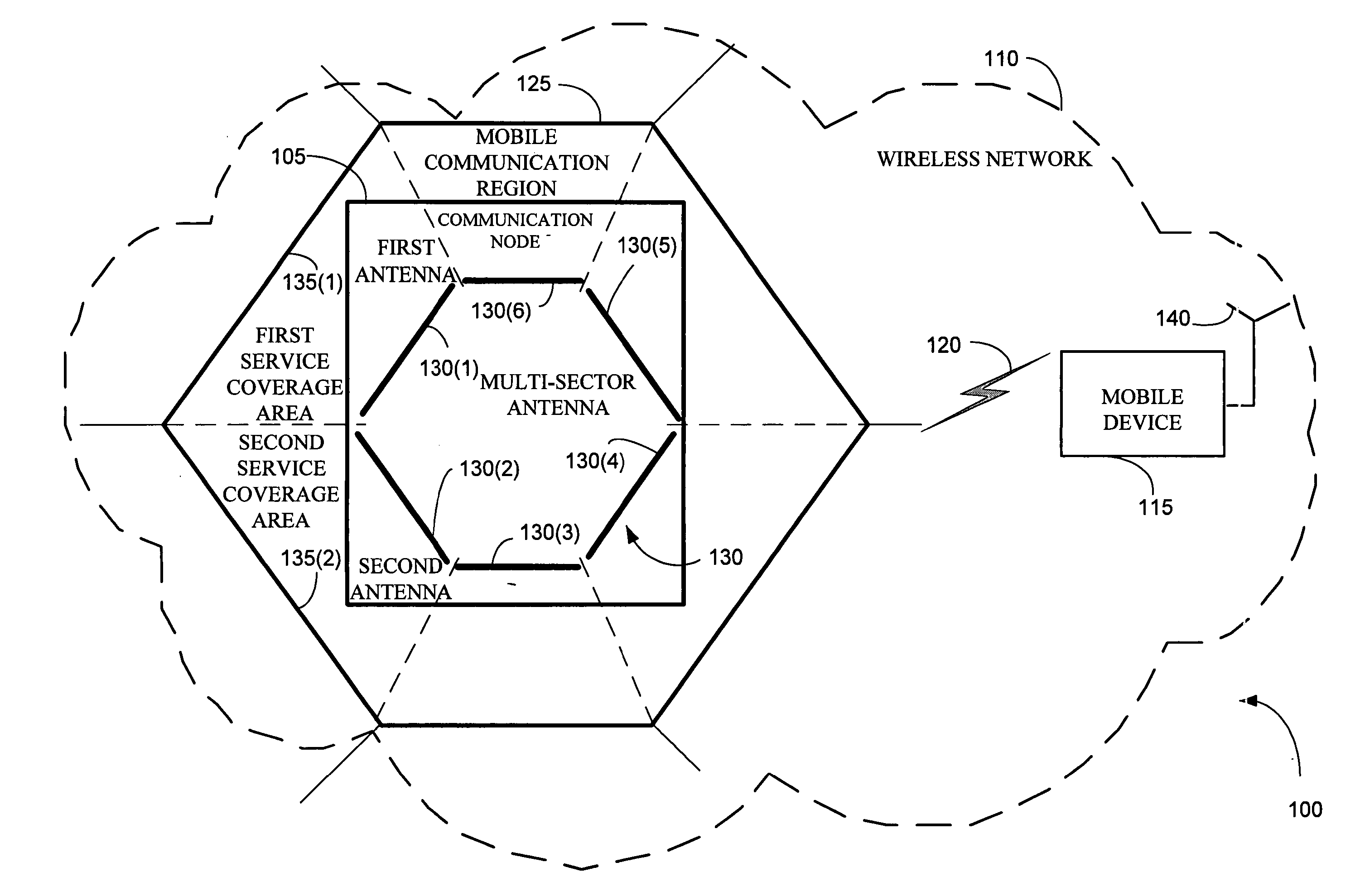
[0033] Generally, a base station includes an antenna arrangement that transmits and receives information from a plurality of mobile devices, e.g., cellular phones, in a cell. The cell may be divided into multiple sectors. The antenna arrangement includes a set of antennas, each of ...


PUM


Abstract

The present invention provides a communication node associated with a wireless network to communicate with a mobile device over a wireless medium across a plurality of mobile communication regions. The communication node comprises an antenna arrangement including a first, a second and a third antenna, wherein the first antenna is primarily associated with a first service coverage area of a first mobile communication region of the plurality of mobile communication regions, the second antenna is primarily associated with a second service coverage area of the first mobile communication region, and the third antenna is primarily associated with a third service coverage area of the first mobile communication region for combining diversity from the first, second and third antennas to fully communicate information to and from at least one of the first, second and third service coverage areas and to partially communicate information to and from at least two of the first, second and third service coverage areas. In one embodiment, a method may adapt a first, a second and a third antenna in a multi-sector antenna arrangement of a base station across cells by combining diversity from the first, second, and third antennas. Such antenna arrangement may reduce installation and alignment costs for a multi-sector antenna while increasing a receive sensitivity and decreasing a transmit power requirement because base station antennas are not deployed in diversity pairs rather are equally distributed.

Description

BACKGROUND OF THE INVENTION [0001] 1. Field of the Invention [0002] This invention relates generally to telecommunications, and more particularly, to wireless communications. [0003] 2. Description of the Related Art [0004] In a telecommunication system, a large geographically distributed network coverage area is typically partitioned into a multiplicity of mobile communication regions, such as cells, where each cell includes a communication node, such as a base station to realize wireless communications with one or more mobile stations or wireless devices within that cell. The network coverage area is commonly based on wireless links that are designed to operate at a minimum level consistent with Quality of Service (QoS) in an area where the mobile station has sufficient power to achieve a target signal-to-noise (SNR) ratio at a cell site that includes the base station. [0005] Continued growth in the number of users of mobile communications means that many wireless network operators...

Claims


Application Information

Patent Timeline
IPC IPC(8): H04M1/00
CPCH01Q1/246Y02B60/50H04W16/30H04W16/00
Inventor GRANT, NEIL GORDONSCARISBRICK, CHRISTOPHER DAVIDCOOPER, STEPHEN
Owner LUCENT TECH INC
Why Eureka
Try Eureka