Mounting Clamp

a technology of mounting clamps and clamps, which is applied in the direction of machine supports, lighting and heating apparatus, lighting support devices, etc., can solve the problems of suspended objects being loosened from their mounts, the installation time is quite long and thus expensive, and the capacity of c-shaped clamps is often insufficient, so as to reduce vibration and dampen vibration

Inactive Publication Date: 2006-11-16
HUNT RONALD DOUGLAS
View PDF6 Cites 58 Cited by
  • Summary
  • Abstract
  • Description
  • Claims
  • Application Information

AI Technical Summary

Benefits of technology

[0015] An additional feature of the preferred embodiment is the inclusion of a pad of resilient material at the back of the plate that comes to rest against the truss as the bolts are tightened. This resilient pad serves to dampen vibrations that may otherwise be transmitted from the truss to the supported object. Reducing vibration also serves to avoid a problem sometimes encountered with the U-bolt mounts in the prior art whereby over time the bolts could work loose from their points of contact at the top of the bar joist angles allowing the entire mount to wander from its original position.
[0016] Alternate embodiments of the present invention allow for securing objects either interior or exterior to a building, under eaves, on walls, or on rooftops behind parapets. The resilient pad may be used to accommodate an irregular mounting surface. For exterior use the pad may also provide the function of weatherproofing.

Problems solved by technology

For heavier loads, or discrete rather than elongated loads, the capacity of the C-shaped clamps is often insufficient.
Although each adapter is relatively inexpensive, its installation can be quite time consuming and thus costly.
Over a period of time, vibration in the building may cause the adapter to become loose from the truss, or may cause the suspended object to loosen from its mount.

Method used


Image

  • Mounting Clamp
  • Mounting Clamp
  • Mounting Clamp

Examples


Embodiment Construction

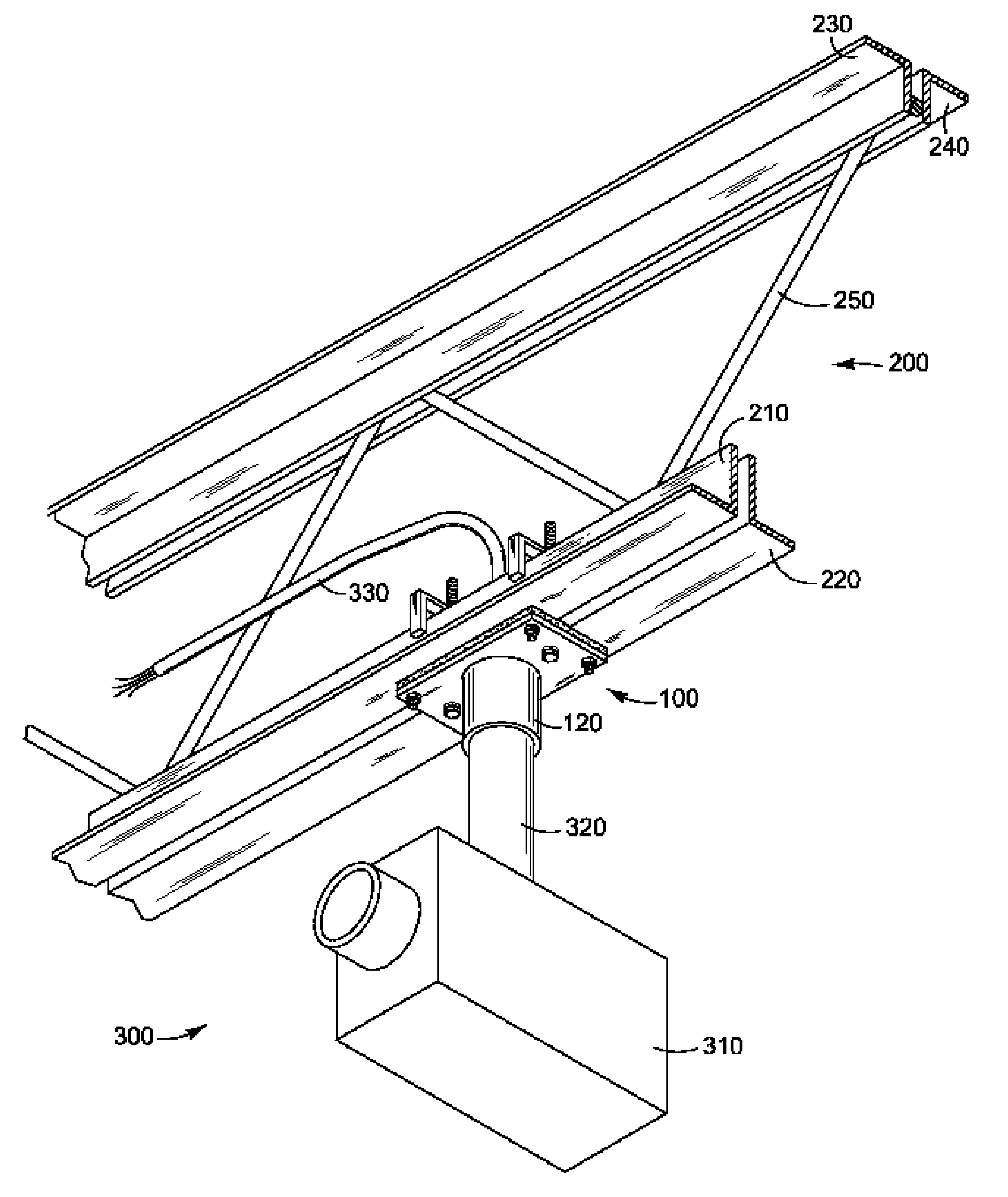
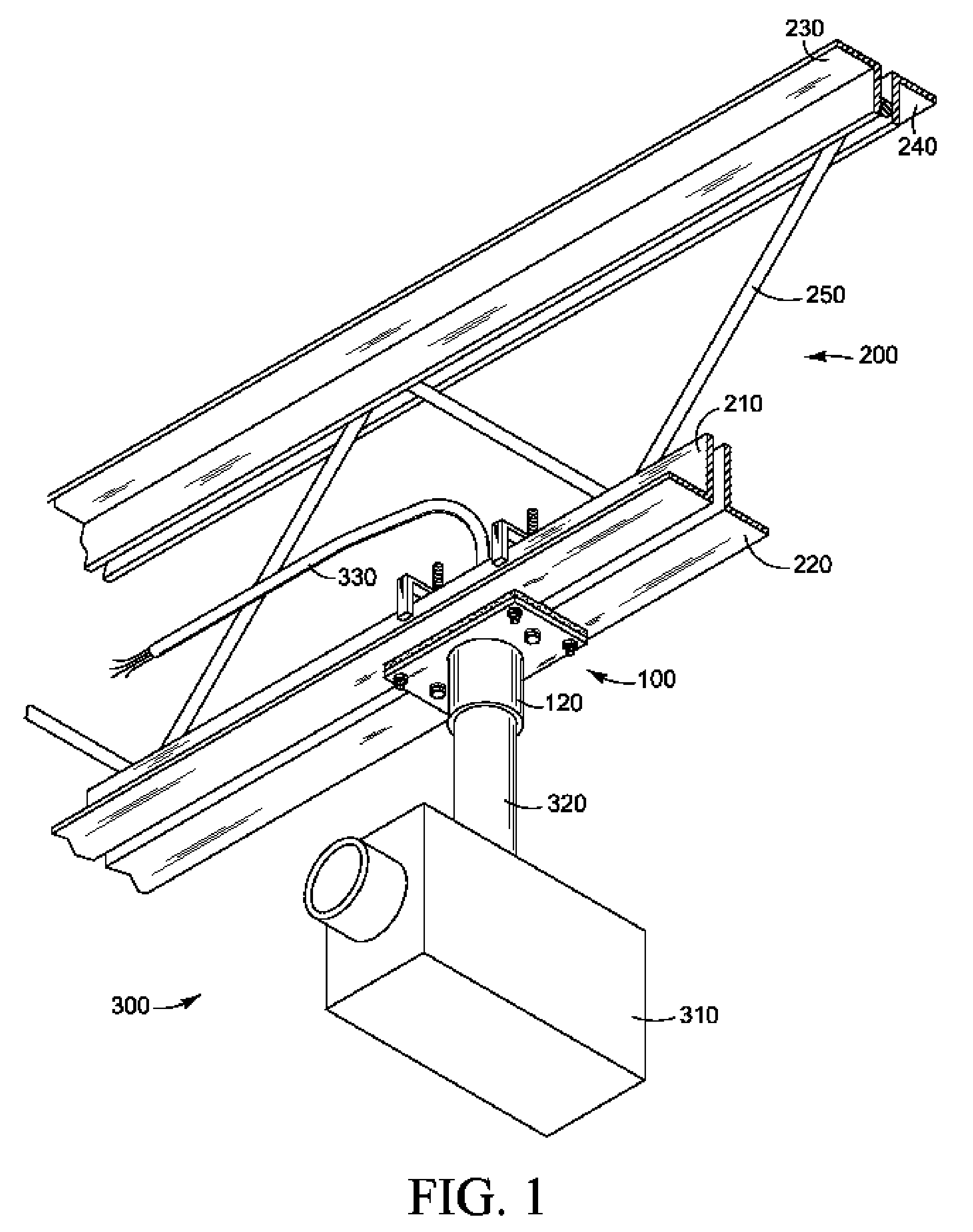
[0065] Refer to FIG. 1 where a truss is illustrated, comprising one pair of angle beams 210 and 220 acting as bar joists which form a lower chord, a second pair of bar joist angle beams 230 and 240 forming an upper chord, and braces 250. While dimensions will vary in keeping with different loads, typically the pair of angle beams forming each chord will be spaced apart by approximately one-half to one inch; that is, the vertical legs of angle beams 210 and 220 will be separated by this amount, and similarly with the vertical legs of angle beams 230 and 240. This small gap allows for connection of the braces 250 between a pair of angle beams. Whether the braces 250 are welded or bolted into place, they are inclined so as to form a truss for reinforcement of the bar joists. While rods may be used for the chords 210-240, and can be accommodated by the clamp of the present invention, angle beams are more common and will be assumed here for descriptive purposes. A clamp 100 of the presen...


PUM


Abstract

This mounting clamp is used as a truss adapter for support of fixtures, electrical and otherwise, from a truss ceiling. The clamp comprises a plate suspended by a pair of upstanding arms, each of which is formed by a bolt connected to an inverted U-shaped rectangular hanger member. The hangers and their associated bolts are inserted upwardly between the spaced beams of a bar joist from below and then the hangers are rotated 90 degrees before they are lowered into place to rest on both of the spaced beams, spreading the load, as the hanger arms are tightened to the plate. The plate carries a connector for mating to the object to be mounted. Leveling screws provide adjustment for orienting the mounted object. A vibration damping pad is included when appropriate. Variations of the clamp may be used in wall or parapet mount configurations.

Description

CROSS-REFERENCES TO RELATED APPLICATIONS [0001] Not Applicable. STATEMENT REGARDING FEDERALLY SPONSORED RESEARCH OR DEVELOPMENT [0002] Not Applicable. FIELD OF THE INVENTION [0003] The present invention relates generally to a device for overhead mounting of an article such as an electrical fixture or appliance to a ceiling, eave or wall. The described invention is particularly suited for ease of installation when suspending a surveillance camera to an open truss ceiling by a person working alone. BACKGROUND OF THE INVENTION [0004] As low cost construction techniques have developed for commercial buildings, there has been a greater utilization of bar joists and trusses, enabling the use of considerably greater unsupported spans than had been allowed by older construction methods. It is becoming commonplace for office and retail building space to be constructed in manners formerly reserved for wholesale or warehousing environments. The appearance of suspended or dropped ceilings has b...

Claims


Application Information

Patent Timeline
Patent Type & Authority Applications(United States)
IPC IPC(8): E04B1/38
CPCE04B9/006F16B2/065F16M13/027F21V21/03F16M13/02
Inventor HUNT, RONALD DOUGLAS
Owner HUNT RONALD DOUGLAS
Why Eureka
Try Eureka