Ejector cycle device

a cycle device and ejector technology, applied in the direction of defrosting, heating apparatus, domestic cooling apparatus, etc., can solve the problems of deteriorating the life of the compressor, flowing noise, and affecting the efficiency of the compressor, so as to prevent the noise of refrigerant flowing

Inactive Publication Date: 2006-11-16
DENSO CORP
View PDF11 Cites 95 Cited by
  • Summary
  • Abstract
  • Description
  • Claims
  • Application Information

AI Technical Summary

Benefits of technology

[0017] In view of the foregoing problems, it is an object of the present invention to provide an ejector cycle device which can prevent a refrigerant flowing noise when a compressor is stopped.

Problems solved by technology

In the process of developing this pressure balance, refrigerant passing through the nozzle portion of the ejector causes flowing noises.
In this case, the life of durability of the compressor is deteriorated.
However, in the process of developing pressure balance when the compressor is stopped, refrigerant passing though the nozzle portion of the ejector and the throttle mechanism of the branch passage causes flowing noises.
When the frost deposits in the three portions, the cooling efficiency of the ejector cycle device is greatly deteriorated.

Method used


Image

  • Ejector cycle device
  • Ejector cycle device
  • Ejector cycle device

Examples


1st embodiment

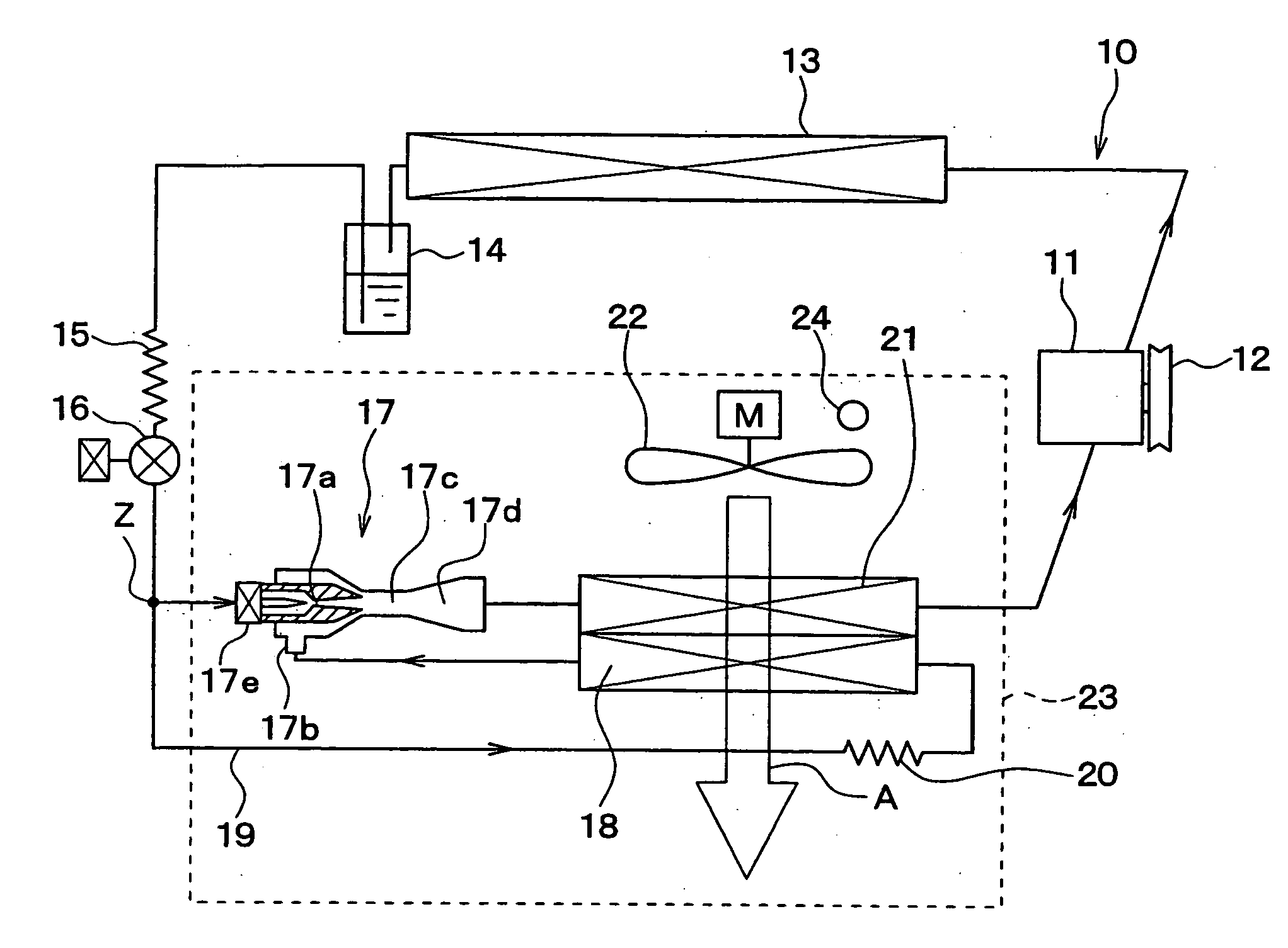
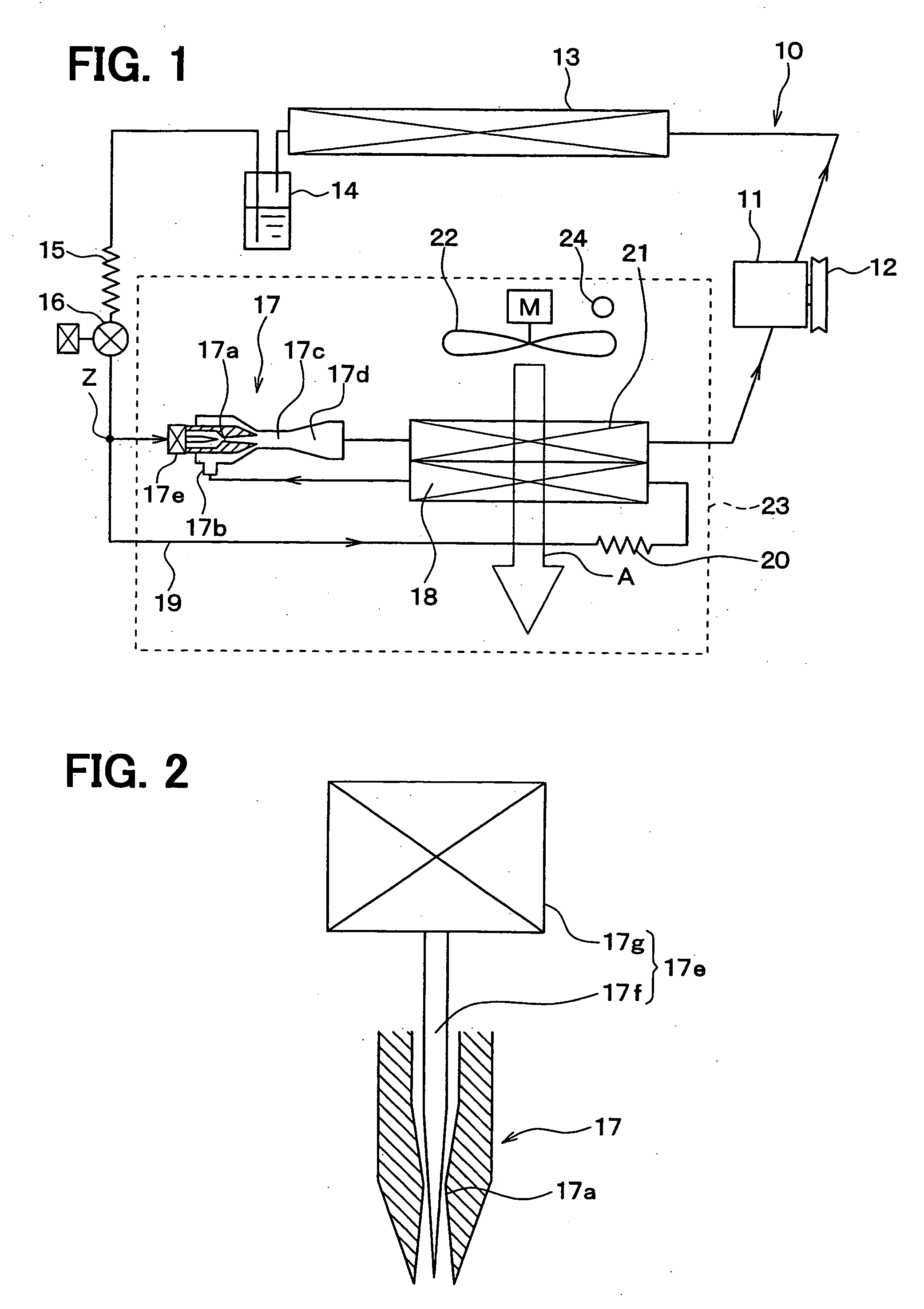
[0090]FIG. 1 and FIG. 2 show the 1st embodiment of the present invention. FIG. 1 shows an example to which an ejector cycle device 10 in accordance with the 1st embodiment is used for a refrigerating device for a vehicle. Here, the refrigerating device for a vehicle of this embodiment cools the inside of a compartment (space) to an extremely low temperature of, for example, approximately −20° C.

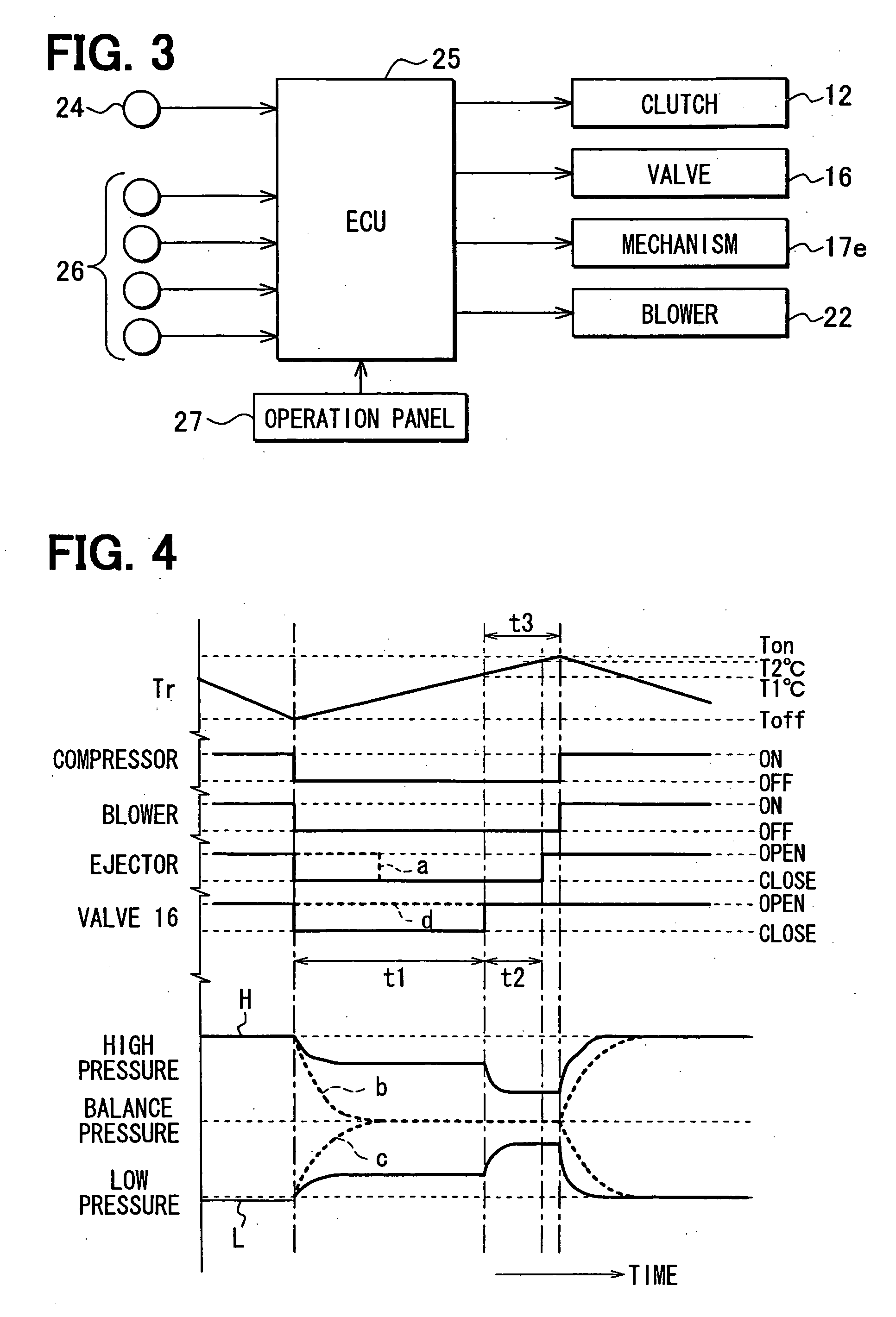
[0091] In the ejector cycle device 10 of this embodiment, a compressor 11 for sucking and compressing refrigerant is rotated and driven by a vehicle driving engine (not shown) via an electromagnetic clutch 12, a belt, and the like. This compressor 11 is connected to and disconnected from the vehicle driving engine by intermittently passing current through the electromagnetic clutch 12, thereby being intermittently operated. That is, the refrigerant discharge capacity of the compressor 11 is controlled by changing the rate of intermittent operation of the compressor 11 by intermittently opera...

2nd embodiment

[0163] In the 1st embodiment, the opening / closing valve 16 is closed in operative connection with the operation of stopping the compressor 11. However, in the 2nd embodiment, as shown in FIG. 6, when the inside temperature Tr of the space to be cooled decreases to the lower limit set temperature Toff, first, the opening / closing valve 16 is closed before the compressor 11 is stopped. With this, the compressor 11 is continuously operated for a specified time t4 with the upstream passage of the branch point Z held shut and then is stopped after this specified time t4 passes.

[0164] Here, the specified time t4 is a period of a pump-down operation in which the compressor 11 draws refrigerant on the low pressure side of the cycle and moves the refrigerant to high pressure side and holds the refrigerant on the high pressure side. By performing this pump-down operation, the amount of refrigerant collected in the first and second evaporators 18, 21 when the compressor 11 is stopped can be fu...

3rd embodiment

[0167] In the 1st embodiment, the throttle mechanism 15 and the opening / closing valve 16 are arranged on the upstream side of the branch point Z on the upstream side of the ejector 17. However, in the 3rd embodiment, as shown in FIG. 8, the throttle mechanism 15 and the opening / closing valve 16 arranged on the upstream side of the ejector 17 in the above-described first embodiment are not arranged, but the opening / closing valve 16 is interposed between the downstream side of the throttle mechanism 20 of the refrigerant branch passage 19 and the upstream side of the first evaporator 18.

[0168] Hence, according to the 3rd embodiment, the opening / closing valve 16 shuts only the passage of the refrigerant branch passage 19. Hence, in the 3rd embodiment, both of the opening / closing valve 16 and the passage opening / closing mechanism 17e of the ejector 17 are brought into a closing state at the same time in operative connection with the operation of stopping the compressor 11. With this, t...


PUM


Abstract

In an ejector cycle device having an ejector, an evaporator is arranged in a refrigerant branch passage connected to a refrigerant suction port of the ejector, an opening/closing member for opening and closing a refrigerant passage is disposed to prevent refrigerant from flowing into the evaporator, and a control unit intermittently controls operation of the compressor. In the ejector cycle device, the control unit brings the opening/closing member into a closing state in a time period for which the operation of the compressor is stopped. Accordingly, it can restrict liquid refrigerant from collecting in the evaporator while the compressor is stopped.

Description

CROSS REFERENCE TO RELATED APPLICATION [0001] This application is based on Japanese Patent Applications No. 2005-142476 filed on May 16, 2005, No. 2005-148470 filed on May 20, 2005, No. 2005-151588 filed on May 24, 2005, No. 2005-213272 filed on Jul. 22, 2005, and No. 2005-219354 filed on Jul. 28, 2005, the contents of which are incorporated herein by reference in its entirety. BACKGROUND OF THE INVENTION [0002] 1. Field of the Invention [0003] The present invention relates to an ejector cycle device having an ejector which has a function for reducing pressure of refrigerant and a function for circulating refrigerant. [0004] 2. Description of the Related Art [0005] This kind of ejector cycle device has been known in JP-B1-3322263, for example. JP-B1-3322263 discloses an ejector cycle device that has a first evaporator and a second evaporator. The second evaporator is arranged on the downstream side of refrigerant flow of an ejector having functions for reducing pressure of refrigera...

Claims


Application Information

Patent Timeline
Patent Type & Authority Applications(United States)
IPC IPC(8): F25B1/06
CPCB60H1/3205F25D21/08B60H2001/3298F25B5/00F25B5/02F25B5/04F25B39/02F25B41/00F25B2341/0011F25B2341/0012F25B2341/0013F25B2400/23F25B2500/27F25B2500/28F25B2600/2501F25B2600/2507F25B2700/2104F25B2700/2106F25B2700/2117B60H2001/3297
Inventor YOKOYAMA, NAOKIOSHITANI, HIROSHITAKEUCHI, HIROTSUGUNISHIJIMA, HARUYUKIIKEGAMI, MAKOTOMAEHARA, TAKUOYAMADA, ETSUHISA
Owner DENSO CORP
Why Eureka
Try Eureka