Switch
a technology of switches and switches, applied in the direction of contacts, contact surface shapes/structures, contact mechanisms, etc., can solve the problems of unstable operation characteristics, prone to dislocation, and difficult manufacture, so as to increase the freedom of selecting a product and widen the use
- Summary
- Abstract
- Description
- Claims
- Application Information
AI Technical Summary
Benefits of technology
Problems solved by technology
Method used
Image
Examples
first embodiment
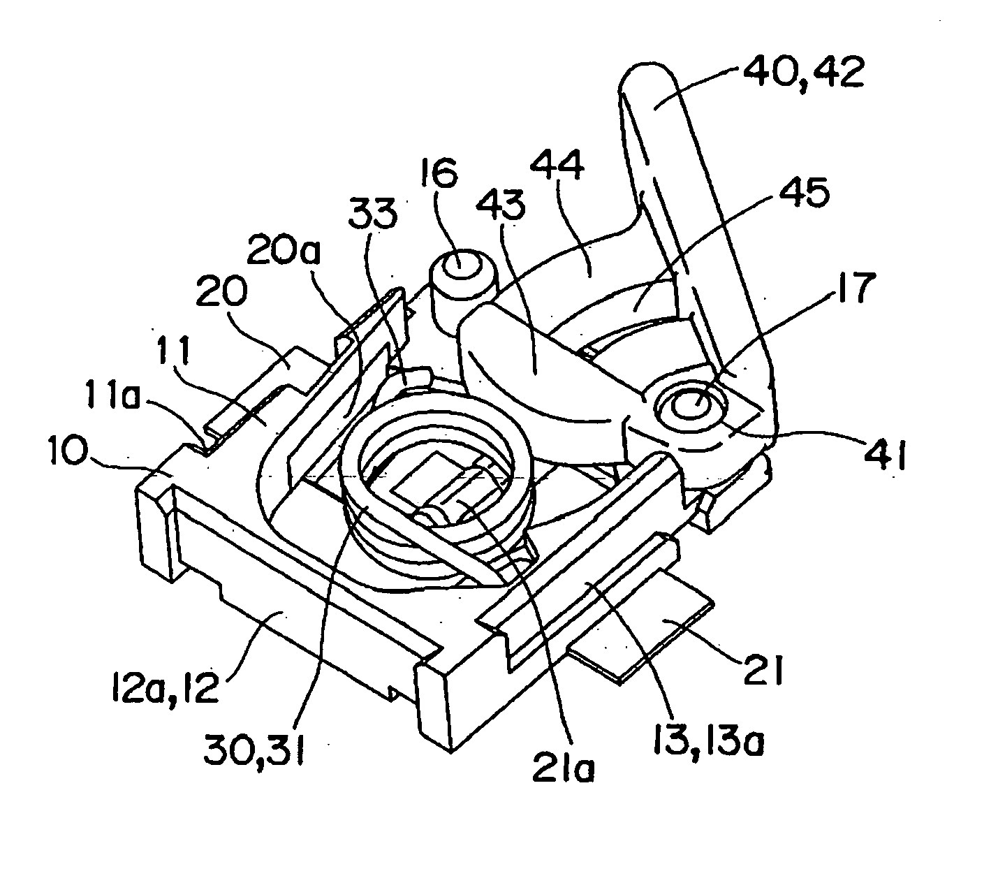
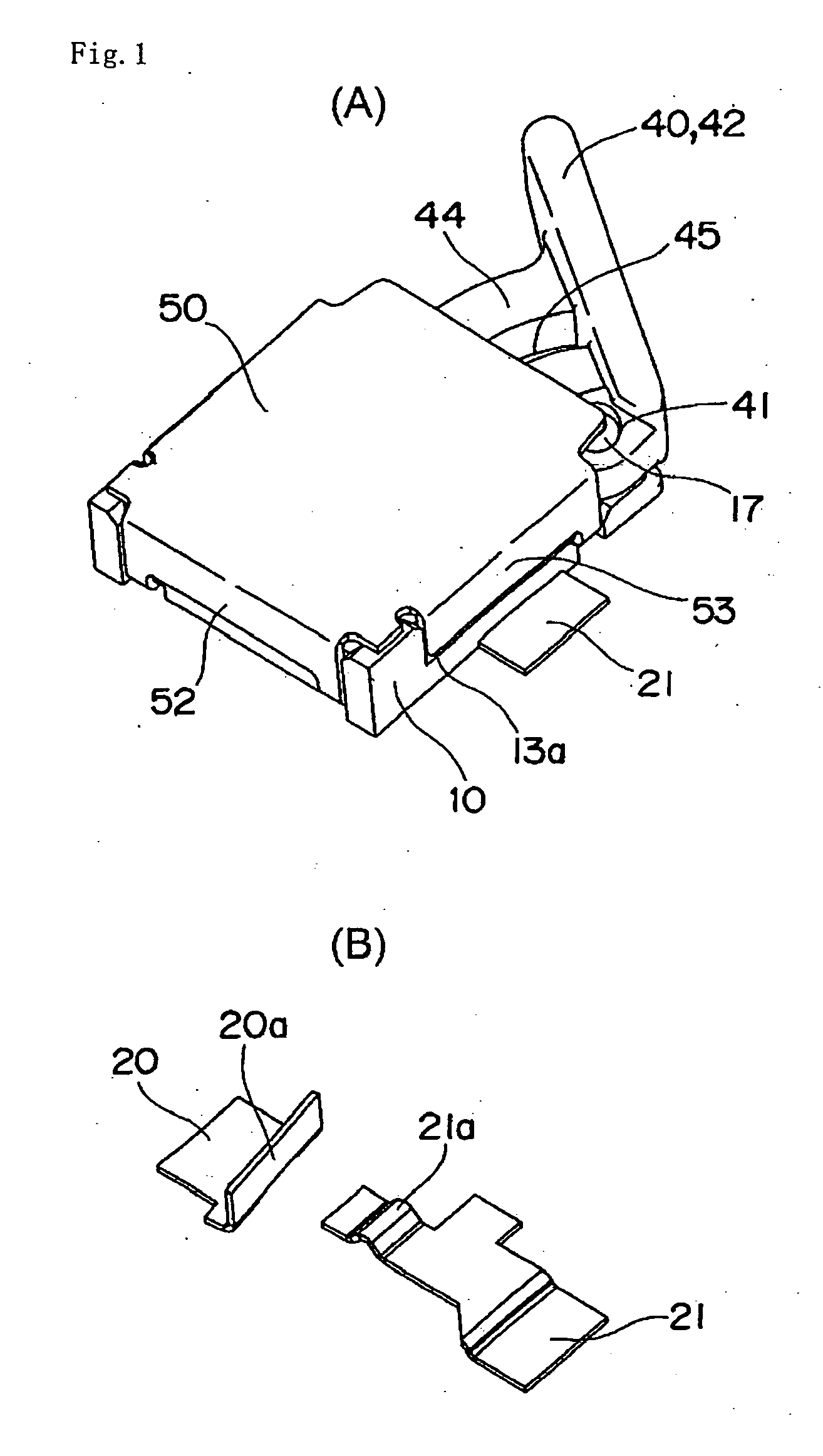
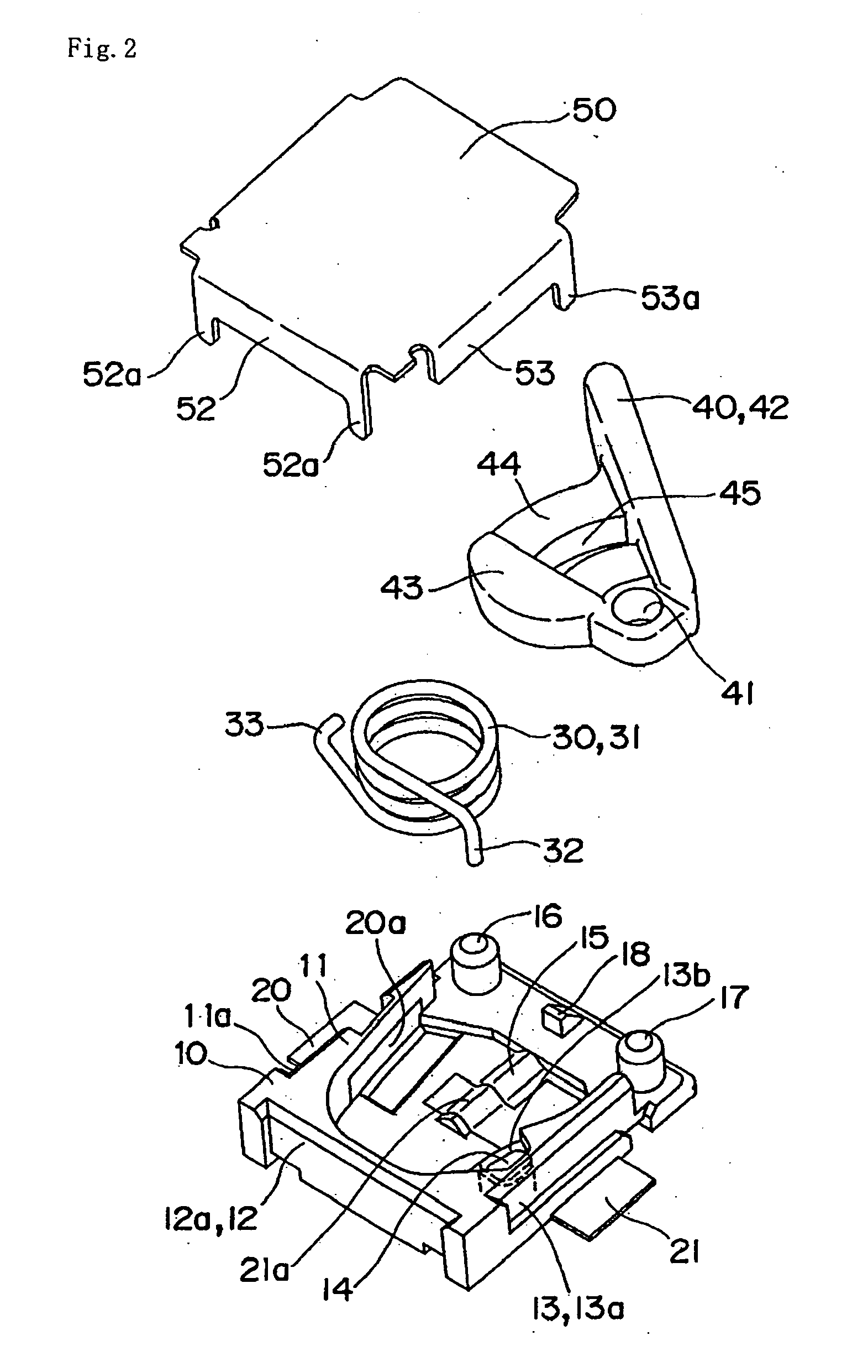
[0047] A first embodiment includes, as shown in FIGS. 1 to 6, a base 10, into which stationary contact terminals 20, 21 are insert-molded, and which is square in plan, a moving contact piece 30 made of a coil spring, an operating lever 40 supported pivotally on the base 10, and a cover 50 that covers the base 10. In addition, an exemplary product as actually assembled has an outside dimension of a total height 0.9 mm, a base width of 3.0 mm, and a length of 3.5 mm.
[0048] The base 10 includes substantially U-shaped side walls 11, 12, 13 provided continuously and protrusively along a peripheral edge of an upper surface thereof, and the stationary contact terminals 20, 21, respectively, are insert-molded on the opposite side walls 11, 13. Positioning steps 11a, 13a, respectively, are provided on outer side surfaces of the side walls 11, 13, on which the stationary contact terminals 20, 21 are insert-molded, while a positioning recess 12a is formed on an outer side surface of the side w...
second embodiment
[0061] A second embodiment provides a normally closed contact type, in which a normally closed stationary contact is arranged on a bottom surface of a base 10 as shown in FIG. 7B and FIGS. 8 to 11.
[0062] That is, as shown in FIG. 8, a normally closed stationary contact 21b is exposed to a surface of a ridge 15 protrusively provided on a bottom surface of the base 10. As shown in FIGS. 9 to 11, when an operating lever 40 is pushed in, a torsional moment acting on a coil portion 31 increases, so that the coil portion 31 slides on the surface of the ridge 15 while the other end 33 slides on a common stationary contact 20a. Therefore, the coil portion 31 of a moving contact piece 30 having come into pressure contact with the normally closed stationary contact 21b is opened relative to the closed stationary contact 21b. When a load on the operating lever 40 is released, the operating lever 40 is pushed back outward by the spring force of the moving contact piece 30 to return to an origin...
third embodiment
[0063] a common stationary contact 20a is exposed to an inner surface of a side wall 11 and a normally closed stationary contact 21b and a normally opened stationary contact 22a are arranged on a bottom surface of a base 10 as shown in FIG. 7C.
[0064] Accordingly, when an operating lever 40 is pushed in, a torsional moment acting on a coil portion 31 of a moving contact piece 30 increases, so that the moving contact piece turns about an end 32 whereby the other end 33 slides on a common stationary contact 20a, and the coil portion 31 of a moving contact piece 30 having come into pressure contact with a normally closed stationary contact 21b contacts with a normally opened stationary contact 22a to perform contact switchover. Since the rest is the same as that in the embodiment described above, the same parts as those in the latter are denoted by the same reference numerals as those in the latter, and an explanation therefor is omitted.
PUM
 Abstract
Description
Claims
Application Information
 - R&D
- Intellectual Property
- Life Sciences
- Materials
- Tech Scout
- Unparalleled Data Quality
- Higher Quality Content
- 60% Fewer Hallucinations
Browse by: Latest US Patents, China's latest patents, Technical Efficacy Thesaurus, Application Domain, Technology Topic, Popular Technical Reports.
© 2025 PatSnap. All rights reserved.Legal|Privacy policy|Modern Slavery Act Transparency Statement|Sitemap|About US| Contact US: help@patsnap.com


