Image processing apparatus and image processing method

a technology of image processing apparatus and image processing method, which is applied in the direction of memory allocation/allocation/relocation, image memory management, instruments, etc., can solve the problems of limiting the throughput of processing, affecting the cost reduction of the entire image processing apparatus, and increasing the cost of the whole image processing apparatus

Inactive Publication Date: 2006-11-16
CANON KK
View PDF22 Cites 30 Cited by
  • Summary
  • Abstract
  • Description
  • Claims
  • Application Information

AI Technical Summary

Benefits of technology

[0009] In order to achieve the above objects, an image processing apparatus according to the present invention is characterized by mainly comprising memory area control means for setting, for image data bitmapped on a first memory, a rectangular area divided in a main scanning direction and sub-scanning direction; address generation means for generating address information to read out image data corresponding to the rectangular area in correspondence with the set rectangular area; memory control means for reading out the image data corresponding to the rectangular area and DMA-transferring the image data to a second memory in accordance with the generated address information; and image processing means for executing image processing for each rectangular area of the DMA-transferred data by using the second memory.

Problems solved by technology

This restricts the throughput of processing.
If the capacity of the line buffer is increased in the hardware configuration of the image processing circuit to improve the processing capability, the cost increases.
This impedes cost reduction of the entire image processing apparatus.
This impedes generalization and cost reduction of the image processing circuit.

Method used


Image

  • Image processing apparatus and image processing method
  • Image processing apparatus and image processing method
  • Image processing apparatus and image processing method

Examples


Embodiment Construction

[0041] A preferred embodiment of the present invention will now be described in detail in accordance with the accompanying drawings.

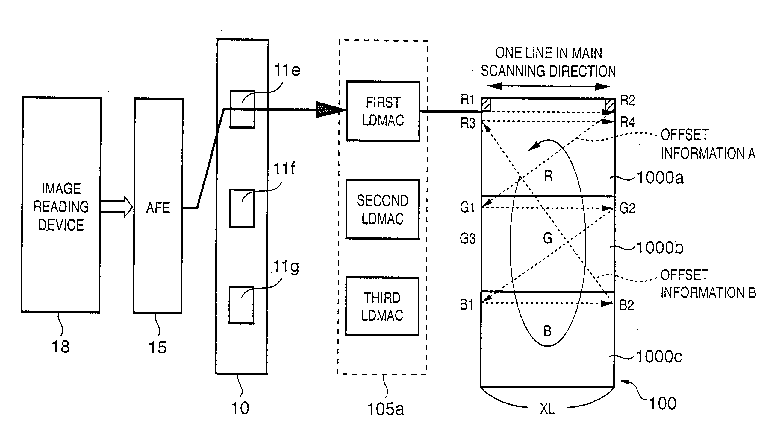
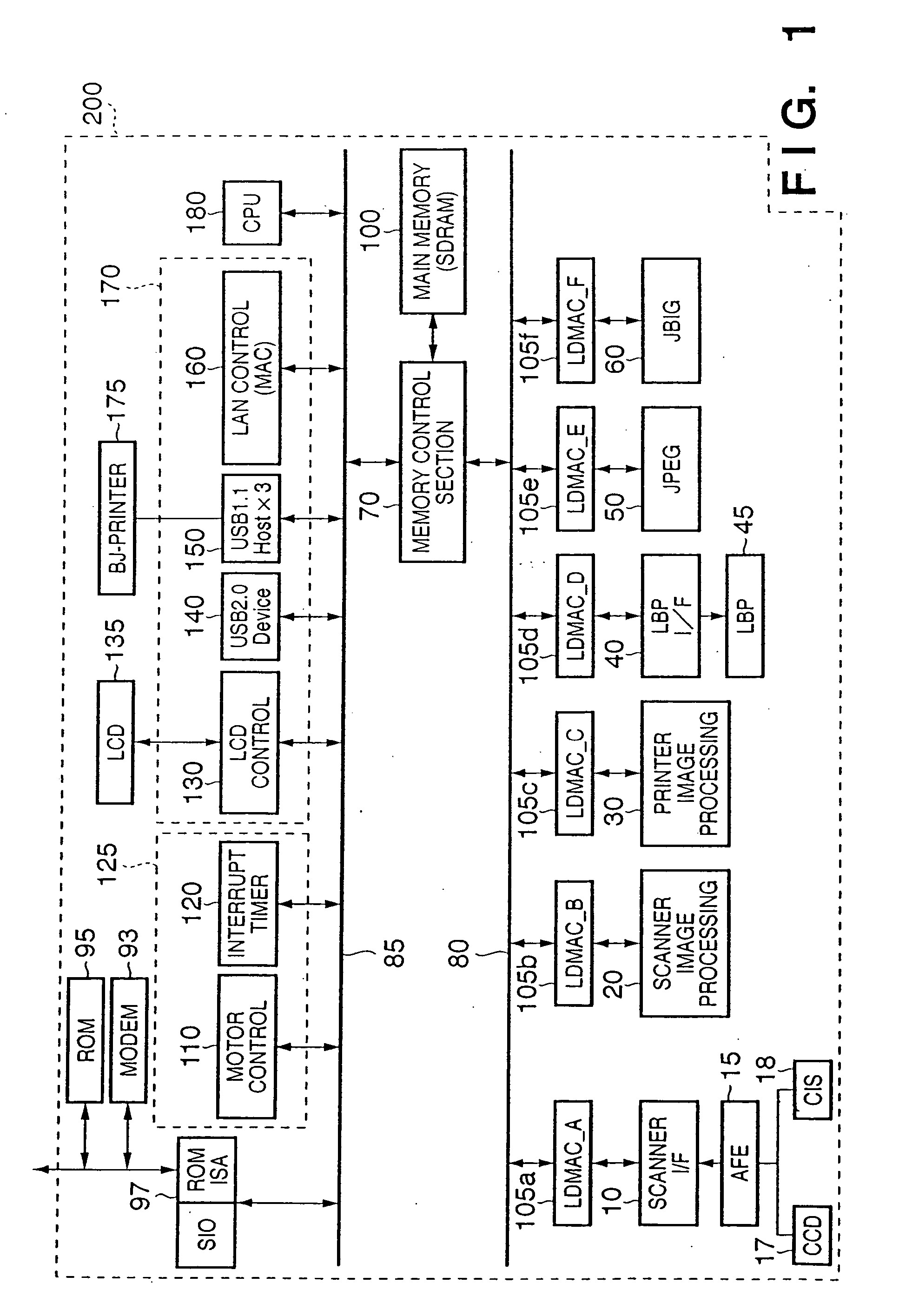
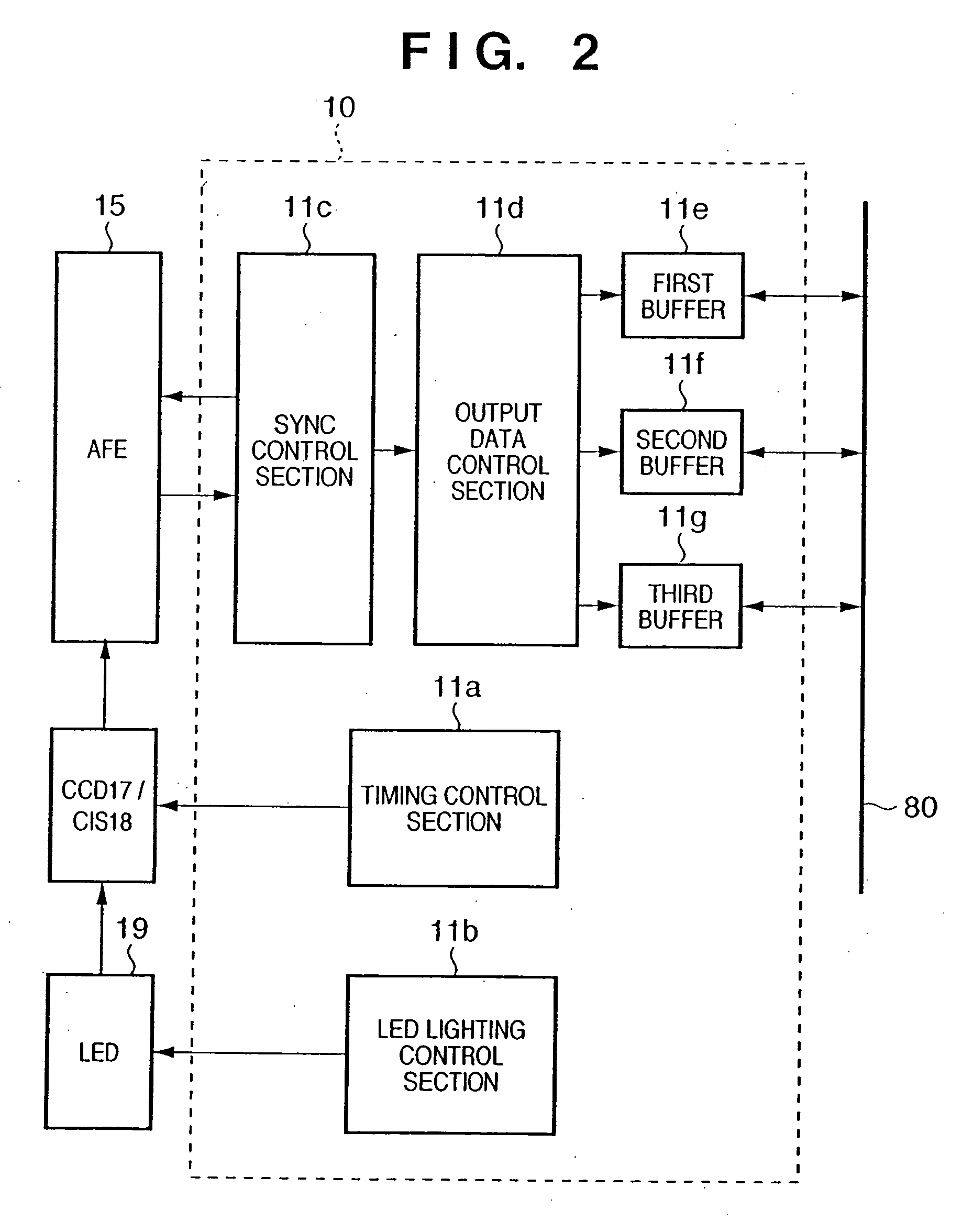
[0042]FIG. 1 is a block diagram showing the schematic composition of an image processing apparatus 200 according to an embodiment of the present invention. A CCD 17 and CIS 18 are connected to a scanner interface (to be referred to as a “scanner I / F” hereinafter) section 10 through an analog front end (AFE) 15. Read data can be input to the image processing apparatus 200 without intervening individual dedicated circuits. Data processing by the scanner I / F section 10 will be described later in detail.

[0043] A scanner image processing section 20 executes image processing corresponding to an image processing operation mode (color copy, monochrome copy, color scan, monochrome scan, and the like) for image data that is bitmapped on a main memory 100 by processing of the scanner I / F section 10. The scanner image processing section 20 will be described later...


PUM


Abstract

To provide an image processing technique compatible with both a CCD and a CIS, which controls storage of image data read by each device in a memory and the read of the stored data for each rectangular area to obtain a high memory efficiency, an image processing apparatus includes a memory area control section which sets, for image data bitmapped on a first memory, a rectangular area divided in a main scanning direction and sub-scanning direction, an address generation section which generates address information to read out image data corresponding to the rectangular area in correspondence with the set rectangular area, a memory control section which reads out the image data corresponding to the rectangular area and DMA-transfers the image data to a second memory in accordance with the generated address information, and an image processing section which executes image processing for each rectangular area of the DMA-transferred data by using the second memory.

Description

FIELD OF THE INVENTION [0001] The present invention relates to an image processing technique which is compatible with both an image reading device (CCD (Charged Coupled Device)) and a CIS (Contact Image Sensor) and controls storage of image data read by each device in a memory and a read of the stored data for each rectangular area. BACKGROUND OF THE INVENTION [0002]FIG. 27 is a block diagram showing the composition of a scanner image processing circuit in a conventional image processing apparatus. As an image reading device, an optical element such as a CCD 2010 or CIS 2110 is used. Data according to a predetermined output format is A / D-converted by a CCD interface (I / F) circuit 2000 or CIS interface (I / F) circuit 2100 and stored in a main memory 2200 for each line in the main scanning direction. In this case, the CCD 2010 outputs data corresponding to R, G, and B in parallel. The CIS 2110 serially outputs the signals of R, G, and B data in accordance with the order of LED lighting...

Claims


Application Information

Patent Timeline
Patent Type & Authority Applications(United States)
IPC IPC(8): G09G5/39G06F12/06G06T1/60
CPCG06T1/60G06T1/0007
Inventor USHIDA, KATSUTOSHINAOI, YUICHIKATAHIRA, YOSHIAKINAKAMURA, YASUYUKIMORISHITA, KOICHIFUKUO, MAKOTO
Owner CANON KK
Why Eureka
Try Eureka